
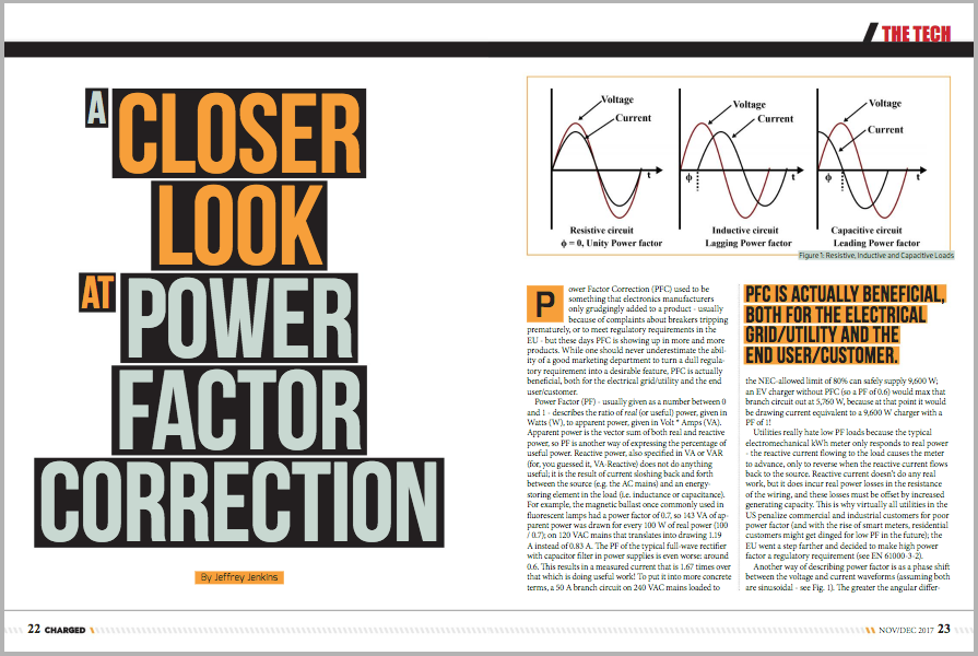
Power Factor Correction (PFC) used to be something that electronics manufacturers only grudgingly added to a product – usually because of complaints about breakers tripping prematurely, or to meet regulatory requirements in the EU – but these days PFC is showing up in more and more products. While one should never underestimate the ability of a good marketing department to turn a dull regulatory requirement into a desirable feature, PFC is actually beneficial, both for the electrical grid/utility and the end user/customer.
Power Factor (PF) – usually given as a number between 0 and 1 – describes the ratio of real (or useful) power, given in Watts (W), to apparent power, given in Volt * Amps (VA). Apparent power is the vector sum of both real and reactive power, so PF is another way of expressing the percentage of useful power. Reactive power, also specified in VA or VAR (for, you guessed it, VA-Reactive) does not do anything useful; it is the result of current sloshing back and forth between the source (e.g. the AC mains) and an energy-storing element in the load (i.e. inductance or capacitance). For example, the magnetic ballast once commonly used in fluorescent lamps had a power factor of 0.7, so 143 VA of apparent power was drawn for every 100 W of real power (100 / 0.7); on 120 VAC mains that translates into drawing 1.19 A instead of 0.83 A. The PF of the typical full-wave rectifier with capacitor filter in power supplies is even worse: around 0.6. This results in a measured current that is 1.67 times over that which is doing useful work! To put it into more concrete terms, a 50 A branch circuit on 240 VAC mains loaded to the NEC-allowed limit of 80% can safely supply 9,600 W; an EV charger without PFC (so a PF of 0.6) would max that branch circuit out at 5,760 W, because at that point it would be drawing current equivalent to a 9,600 W charger with a PF of 1!
Utilities really hate low PF loads because the typical electromechanical kWh meter only responds to real power – the reactive current flowing to the load causes the meter to advance, only to reverse when the reactive current flows back to the source. Reactive current doesn’t do any real work, but it does incur real power losses in the resistance of the wiring, and these losses must be offset by increased generating capacity. This is why virtually all utilities in the US penalize commercial and industrial customers for poor power factor (and with the rise of smart meters, residential customers might get dinged for low PF in the future); the EU went a step farther and decided to make high power factor a regulatory requirement (see EN 61000-3-2).
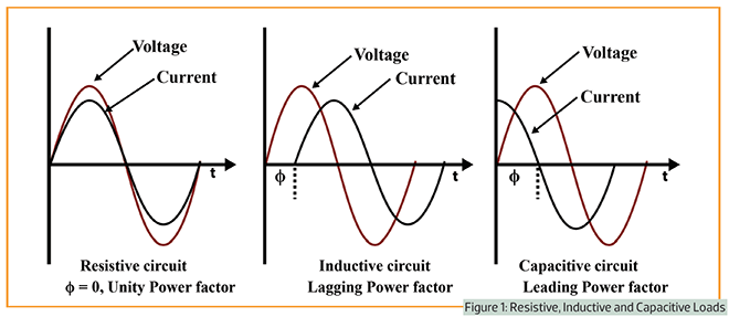
Another way of describing power factor is as a phase shift between the voltage and current waveforms (assuming both are sinusoidal – see Fig. 1). The greater the angular difference (up to the maximum of 90°) the higher the reactive power component (and the lower the power factor). Europeans seem to be fond of this approach, and it can be identified by the use of the phrase “cos phi” or “cos Φ” followed by a number between 0 and 1 (so, same as PF, which can be confusing, even to engineers). For example, if cos Φ is 0.85 then the phase shift between voltage and current is 31.8°.
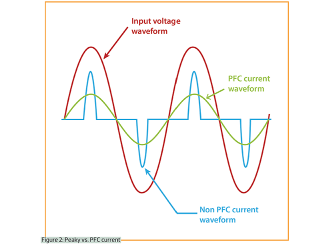
These days a different cause of poor power factor has become more prevalent: capacitor input filters in switch-mode power supplies draw “peaky” currents from the AC mains (see Fig. 2). The peak of the current nearly coincides with the peak of the voltage, but the PF is low because current is only drawn over a narrow portion of the sine wave. This greatly increases the harmonic content (the total harmonic distortion, or THD) of the current waveform relative to the voltage, and limiting THD is the precise aim of directive EN 61000-3-2 (often referred to as the European “power factor” directive). This issue became more prevalent as semiconductors replaced tubes (valves) because tube rectifiers have a fairly low peak current rating, so some form of current-limiting impedance between the rectifier and filter capacitor was required. For low-power (or “built to a price”) circuits a resistor would suffice, but for higher-power and/or better-quality circuits a choke (filter inductor) was ideal, because it improved voltage regulation and also reduced peak current (using a resistor to limit charging current into the filter capacitor worsens voltage regulation, of course). The ratio of the peak to RMS value of a waveform, or crest factor, is 1.414 for a sine wave supplying a pure resistance, but with a suitable value choke, the crest factor drops to near 1. Semiconductor diodes are much more tolerant of high peak currents, however, so it wasn’t long before the bulky and often expensive choke was dropped from power supply designs. Like so many things in engineering, though, this had some unintended consequences, because the crest factor of a straight capacitor input filter is typically between 2 and 10.

Regardless of the regulatory requirements or the behavior of any particular circuit, the goal of PFC is to make the load behave as much like a pure resistance as possible: if the mains voltage waveform is a sinusoid then the load current should also be a sinusoid (with as close to 0° phase displacement as possible). Power factor correction can be as simple as wiring some capacitors across the mains, or as complicated as using a digital signal processor to control a 3-phase Vienna rectifier.

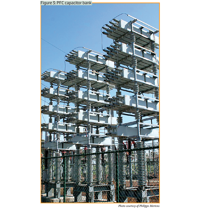
Starting with the simplest solution, a capacitor can be wired across the AC mains to null out any inductance in the wiring up until that point or in the downstream load (see Fig. 3). It is also theoretically possible to wire an inductor in series with each phase of the AC mains to counteract any capacitive character in the load, but this is rarely (read: never) done because the grid wiring is already highly inductive to begin with (approximately 0.6 to 0.8 mH per km) and inductors are big, heavy and expensive. A related passive PFC technique is to use a resonant LC network tuned to a specific (always odd) harmonic to notch it out. This is commonly done in high-power products in which implementing some form of active PFC would be cost-prohibitive, unduly affect reliability, or both. One other method of correcting power factor that is definitely only used at very high power levels – think megawatt scale – is the wound-rotor synchronous motor. Over-exciting the field (rotor) will result in the stator windings presenting a leading (i.e. capacitive-like) PF, while under-exciting the rotor results in a lagging PF.
Active PFC uses semiconductor switches and energy storage elements (again, inductors and/or capacitors) to shape input current so that it tracks input voltage while (usually) delivering a semi-regulated output voltage. The two most common techniques for active PFC are the non-isolated boost converter pre-regulator (which is followed by another switch-mode converter to provide isolation, voltage transformation, etc) and the discontinuous mode (DCM) isolated flyback converter (which is pretty much the only practical “single stage” converter solution – that is, it performs PFC, isolation, etc, all at once). There are many other topologies for accomplishing active PFC, but most of them – especially the other single-stage approaches – are either academic curiosities (good for getting a paper published and not much else), or otherwise not (yet) commercially attractive.
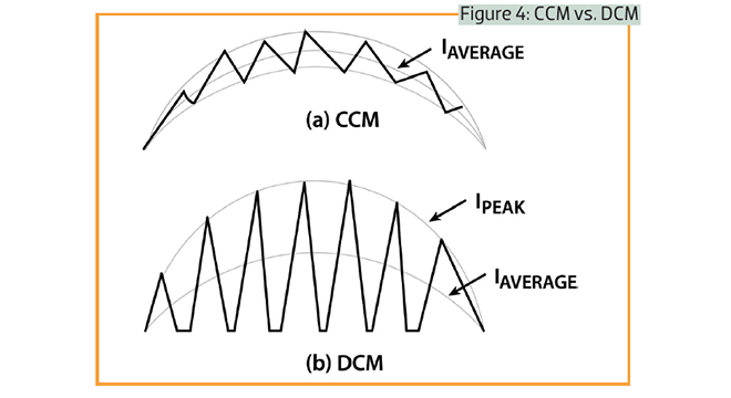
The DCM flyback is the isolated version of the buck-boost converter, one of the three canonical switch-mode converters (the others being the buck and the boost). It is very popular at low power levels (up to 100 W) because it can handle a very wide input voltage range, deliver one or more transformer-isolated output voltages, and automatically perform PFC as long as the bandwidth of the output voltage regulation loop is really low (usually 5 or 6 Hz). This makes it unsuitable for driving highly dynamic loads, but it’s perfectly fine for charging a laptop or cell phone battery. Another disadvantage of the DCM flyback – and the reason it is confined to relatively low power levels – is that it subjects the switch/primary to high peak currents relative to its power throughput. This is because the current through the flyback primary drops to zero each switching cycle in DCM (see Fig. 4). Operation in CCM mitigates that problem, but peak current is still higher for the buck-boost compared to the boost.

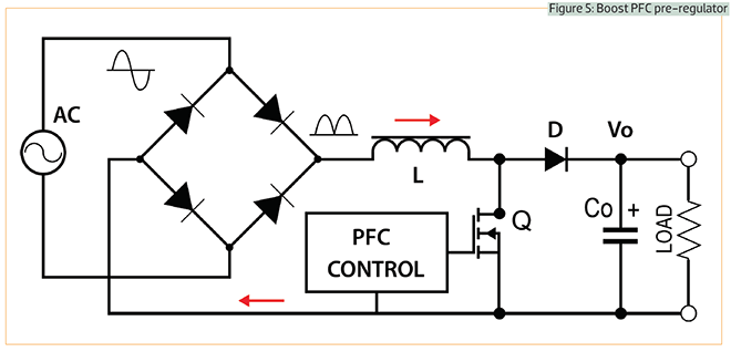
High-power devices like EV chargers – whether a compact onboard type rated for 3 kW or a CHAdeMO 100 kW monster – invariably use a boost converter (see Fig. 5) to perform active PFC. A boost converter periodically shorts an inductor across the incoming supply, causing energy to build up in it, then when the switch opens an output diode directs that energy to a storage capacitor. The inductor acts like a current source in series with the input, then, so the output voltage is always higher than the input; in the case of 120 VAC mains, the output must exceed 170 V, while for 220-240 VAC mains it must exceed 340 V. Consequently, the output voltage of a boost PFC converter is typically set to 380-400 V to allow for worldwide operation. Note, however, that the output is not isolated from the input in a boost converter, while the output voltage regulation loop must be very slow to perform PFC – the same as with the DCM flyback – hence another switch-mode converter is commonly used after the boost PFC stage to provide isolation and tighter regulation.
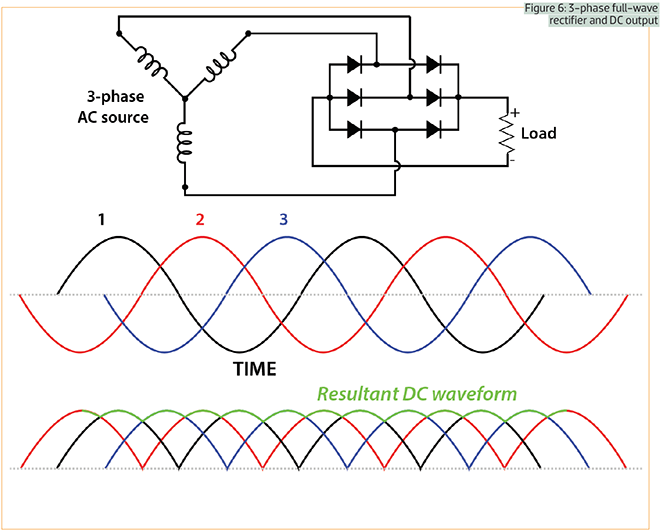
Within reason, there is no real upper power limit for the CCM boost converter, but at the point at which it makes more sense to use 3ɸ (3-phase) AC mains – usually around the 10 kW level – a difficulty arises: it is not possible to both perform PFC and minimize line current distortion in each phase if the mains are full-wave rectified first, as is done in single-phase operation. This is because the instantaneous value of the voltage of any one phase at any specific point in time is lost in the resultant DC waveform (see Fig. 6), and this information is necessary to program a sinusoidal current in each phase. A single-switch boost converter at the output of the 3ɸ rectifier can bring the PF up to around 0.9, but with very high THD in the current waveform, because it will effectively result in square wave currents being drawn from each phase.

Thus, DC Fast Chargers (DCFCs) – which are usually supplied by 3ɸ AC mains – must either use a separate boost converter on each phase, or else resort to more complicated schemes, such as a PWM active rectifier. The simplest example of the latter is the same inverter circuit that is used to drive the traction motor, except operating in reverse (that is, it converts 3ɸ AC into DC, rather than the other way around). However, even the EU doesn’t (yet) mandate PF or THD limits for high-power, hard-wired devices like DCFCs, so if any PFC is performed it will likely be with the aforementioned single-switch boost converter rather than a PWM active rectifier.
Read more EV Tech Explained articles.
This article originally appeared in Charged Issue 34 – November/December 2017 – Subscribe now.