Contactors may not be the sexiest component in an EV, but they are critical both for safety and general functioning. Basically a heavier-duty version of the relay, a contactor is used to switch power to any of the loads supplied by the traction battery in an EV. The motor drive, the heating and cooling systems, the DC/DC converter that supplies all the 12 V loads, and anything else that draws more than a few amps from the traction battery, will almost certainly be switched with a contactor.
Contactors, relays and solenoids are all names for an electromechanical switch. Usually an electromagnet is used to operate the switch – a coil pulling in a steel plunger – but motors have also been used, particularly at very high power ratings or when “latching” operation without requiring continuous energizing is required (that is, no power is required to maintain the switch in either state). Whether you call an electromechanical switch a contactor, a relay or a solenoid depends more on power rating and industry/application than any formal definition. Typically a contactor refers to a high-power device with a limited number of “poles,” or individual switches (one to three most commonly), and which only offers a single “throw,” or on/off action (rather than “dual throw,” or A/B action). Relays tend to be smaller devices rated for 20 A or less and with much more variety in poles and throws. The term solenoid used to refer to all contactors, but these days it is pretty much only used to describe the specialized contactor on ICE starter motors which both energizes the motor (i.e. the contactor function) and which moves the pinion gear to engage the ring gear on the engine (i.e. the solenoid function).
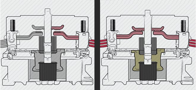
Despite being a nearly obsolete terms these days, solenoid is actually a rather descriptive one for modern contactors and relays as it refers to an electromagnet operating a plunger. A solenoid is a cylindrical coil of wire, while the plunger is a rod of magnetically soft material (that is, one that resists being permanently magnetized). When the coil is energized it creates a magnetic field that pulls in the plunger; all that is required to turn a solenoid into a contactor, then, is to attach the plunger to a plate with a pair of contacts on either side which face another pair of fixed contacts. In the most common construction, Normally Open (NO), a spring holds the movable contacts away from the fixed ones until the solenoid coil is energized. For Normally Closed (NC) action the construction is inverted, with the spring holding the movable contacts against the fixed ones until the coil is energized. One subtle caveat of the NC construction is that the force exerted by the spring must be lower than what the coil is capable of exerting at the beginning of its pull (when it is at its weakest), otherwise the coil would not be able to move the plunger at all. In practice, this means the NC contacts are far more susceptible to bouncing open and closed from shock or vibration, which greatly reduces their lifespan and current rating.
For AC, low-voltage DC (<24 V) and moderate-current (<200 A) applications, the simple construction described above can provide years of service before the contacts are too damaged to function. As both the operating current and, especially, the DC voltage increase, however, additional measures must be taken for the contactor to survive even one switching cycle, much less the many tens to hundreds of thousands typically expected. Circuit conditions must also be considered, as well as the operating environment (temperature, amount of vibration and even orientation can have an effect).
The three types of circuits that a contactor might face are (predominantly) resistive, capacitive or inductive in nature (real circuits have all three qualities, but one does tend to dominate). A heating element is a classic example of a resistive load, and tends to be a fairly benign one for any contactor. Most motors are inductive in nature (one notable exception: over-exciting the field of a wound-field synchronous motor makes it appear capacitive, and can even be used to correct power factor), so the contactors used to select between forward and reverse operation of a series DC or a 3-phase industrial motor must be designed to withstand a highly inductive load. Since modern EVs use inverters, there is no need for these types of contactors in them. However, the input to any switchmode power converter – especially the traction inverter – invariably appears capacitive in nature, and this presents an extreme risk of contact welding upon closure if the capacitance is not charged up to near (but not the same as) the same voltage as the supply. Bringing the voltage on the bus capacitance up to near that of the supply is called, “precharging,” and it is usually done with a separate, smaller contactor in series with a resistor – to limit charging current – that is wired in parallel with the main contactor. The reason why it is not good to precharge the bus capacitors to the same voltage as the supply – so that there is zero voltage differential – is because then no current will flow through the contacts at the moment of closure, a condition called, “dry-switching,” which can actually cause the contacts to become more resistive over time. Consequently, contactors intended for use in EVs usually advise ending precharge when the voltage differential is around 5 V so that a reasonable current will flow at the moment the contacts meet.
Opening a contactor that is looking into a capacitive circuit is generally a benign event even if current is still flowing. This is because an arc requires a voltage difference to form, and capacitors resist a change in voltage; the capacitance in the load stops the change in voltage needed to form an arc. Conversely, inductance resists a change in current and will create whatever voltage is necessary to maintain said current, hence a contactor will not experience adverse conditions when closing into an inductive load, but will if opening an inductive load while current is still flowing. If it is not possible to ramp down current in an inductive load before opening the contactor then a “snubber” must be used. A snubber can be a device placed across the contactor or the inductive load which starts conducting above a certain voltage or it can be a series RC network placed across the contactors, with R chosen to limit the discharge current when the contactor closes again (because otherwise it would be shorting out a charged capacitor – i.e. the same reason why precharging is necessary).
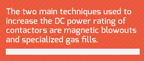
The two main techniques used to increase the DC power rating of contactors are magnetic blowouts to push arcs away should they form, and specialized gas fills to either inhibit arcing or to prevent contact oxidation if some arcing is unavoidable. Magnetic blowouts, as the name implies, are simply magnets placed near the contacts so that their field will push away any arc that forms upon contact opening. One caveat is that current must flow in one direction through the contactor, as indicated by polarity markings next to each contact; if the contactor is wired up backwards then the magnetic blowouts will instead suck any arcs towards them – generally not a good thing. Magnetic blowouts basically force the arc to travel over a longer distance, and since voltage drop across an arc is directly proportional to distance traveled (and relatively insensitive to current – behaving as a negative resistance, in effect) this will cause the arc to extinguish sooner, and without requiring excessive separation of the movable and fixed contacts. Magnetic blowouts do not stop an arc from forming in the first place, nor can they mitigate damage to the contacts from any arcing that does occur.
Hermetically sealing the contactor and either evacuating most of the air or else replacing it with a special gas or gas mixture can reduce damage to the contacts from arcing, and even increase the voltage rating. Evacuating the contactor is primarily reserved for switching high-voltage (>3 kV or so) and high-power RF, while gas fills – primarily nitrogen, hydrogen and sulfur hexafluoride (SF6), either alone or in mixtures – are commonly used everywhere else. Simply excluding oxygen from the contactor will stop oxide formation, but these fill gases also have other useful properties which can improve contact life and/or voltage rating. SF6 has a much higher dielectric strength than air (~3x) and higher thermal conductivity, but its ionization products (that is, the products formed from arc plasma) are corrosive, so it tends only to be used in AC switchgear. Hydrogen has a lower dielectric strength than air (around 35% less) but it is often used in DC switchgear because it rapidly extinguishes arcs and it has a surprisingly high heat capacity for such a low-density gas (usually heat capacity goes up with density). Its main downside is that it tends to diffuse right through the walls of just about any container holding it, including solid steel, and can form complexes called hydrides along the way that can make the metal quite brittle. Lastly there is nitrogen, which seems to be gaining momentum as the fill gas of choice because it has a slightly higher dielectric strength than air (+15%), is relatively inexpensive and does a decent enough job by itself. One potential downside of nitrogen is it can form extremely hard (and poorly conducting) metal nitrides when an arc both ionizes it and vaporizes some of the metal from the contacts; the presence of magnetic blowouts can circumvent this issue by pushing any arcs that form away from the contacts.
The next thing to be considered is the construction of the contacts themselves: their shape, base material and surface plating all play key roles in contactor operation and lifespan. There is a witch’s brew of variety here, with dozens of combinations of metals, shapes and surface plating. Two important details to keep in mind about any mechanical switch – whether manually or electrically operated – is that the initial meeting of two contacts is always at a single point, and that contacts invariably bounce several times before finally closing for good. The former simply means that the surface of each contact looks like treacherous mountain terrain when viewed microscopically, even when polished to a mirror finish. Since contact area must go up with current rating (at least until room-temperature superconductors are a reality), so must the force applied to the contacts to quite literally smash them together. This is also why dry-switching is bad for heavy current switches: the current which flows at the very moment of initial contact is concentrated on a relatively small area which tends to soften, if not melt, the microscopic peaks and valleys. Contact bounce is equally unavoidable as there must be some springiness in the contacts for them to have a chance of meeting. If the load is capacitive then contact bounce is a non-issue; for resistive and, especially, inductive loads, each time the contacts rebound from each other an arc may form, but because the contacts soon close again (and perhaps bounce several more times), this arcing doesn’t cause as much damage as would result from, say, interrupting a heavy inductive load.
Lastly, contactors tend to be one of the least reliable components in any high-power system because they are electromechanical devices with a difficult job to do. Unfortunately, there isn’t really a good “solid state” alternative, to use a term from a bygone era when transistors first started to replace vacuum tubes. This is because no semiconductor switch can truly replicate an open circuit when turned off (some leakage current will always flow), and even though contactors can fail by welding closed, this is a much less frequent failure mode than it is with semiconductor switches. Finally, the semi in semiconductors means that they exhibit a higher bulk resistivity than even the most resistive metal conductor, so they simply can’t handle as much peak power as a mechanical switch of equivalent area. As much as engineers like to grouse about contactors, it appears they will be with us for quite some time to come.
Read more EV Tech Explained articles.
This article originally appeared in Charged Issue 36 – March/April 2018 – Subscribe now.