
Hairpin windings squeeze more copper into a motor’s stator, but the gains depend on frequency, current, insulation and process cost.
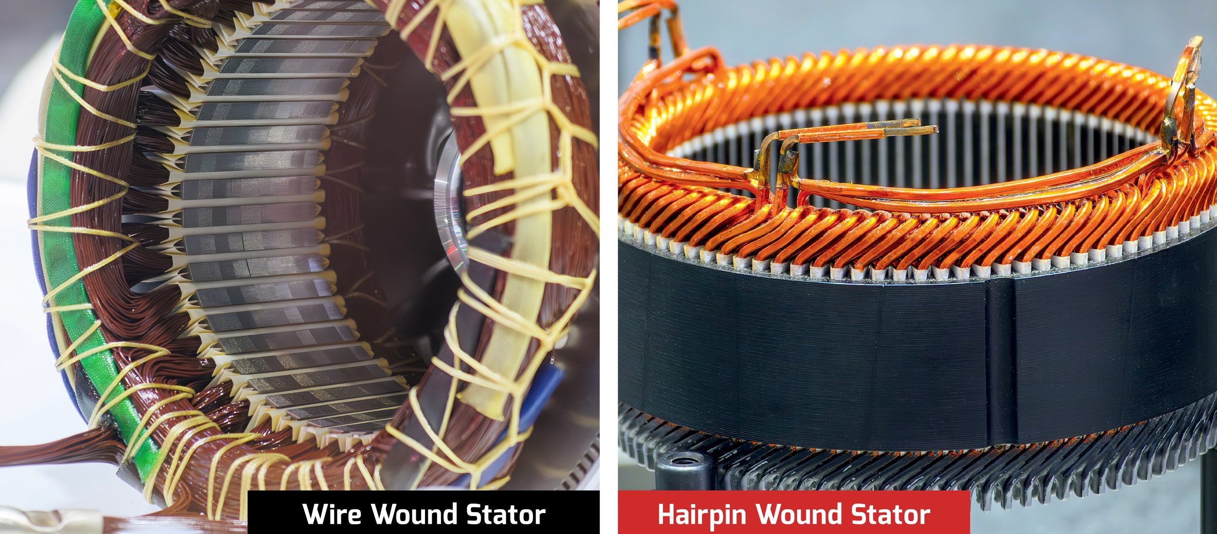
The evocatively-named hairpin winding has been touted by various motor manufacturers as the next step in the evolution of EV traction motors for, oh, a good 10-15 years at this point. But the traditional process of constructing stator windings out of individual strands of magnet wire is still with us, and likely will be for decades to come, because hairpin windings are more of a complementary technology than one destined to upend tradition. In most applications there might only be a slight advantage for one winding technology over the other, especially when manufacturing and lifetime operational costs are factored in, but that doesn’t mean there are no cases in which one construction will prove to be clearly superior to the other.
The traditional method of constructing a motor winding from individual strands of round (or less commonly, square) magnet wire is supremely flexible with respect to the wire gauge that can be handled, the number of turns, the number of wires in parallel, and whether the windings are concentrated or distributed (more on that below). There is also the not-to-be-underestimated 100+ years of manufacturing experience.
The slot-fill problem
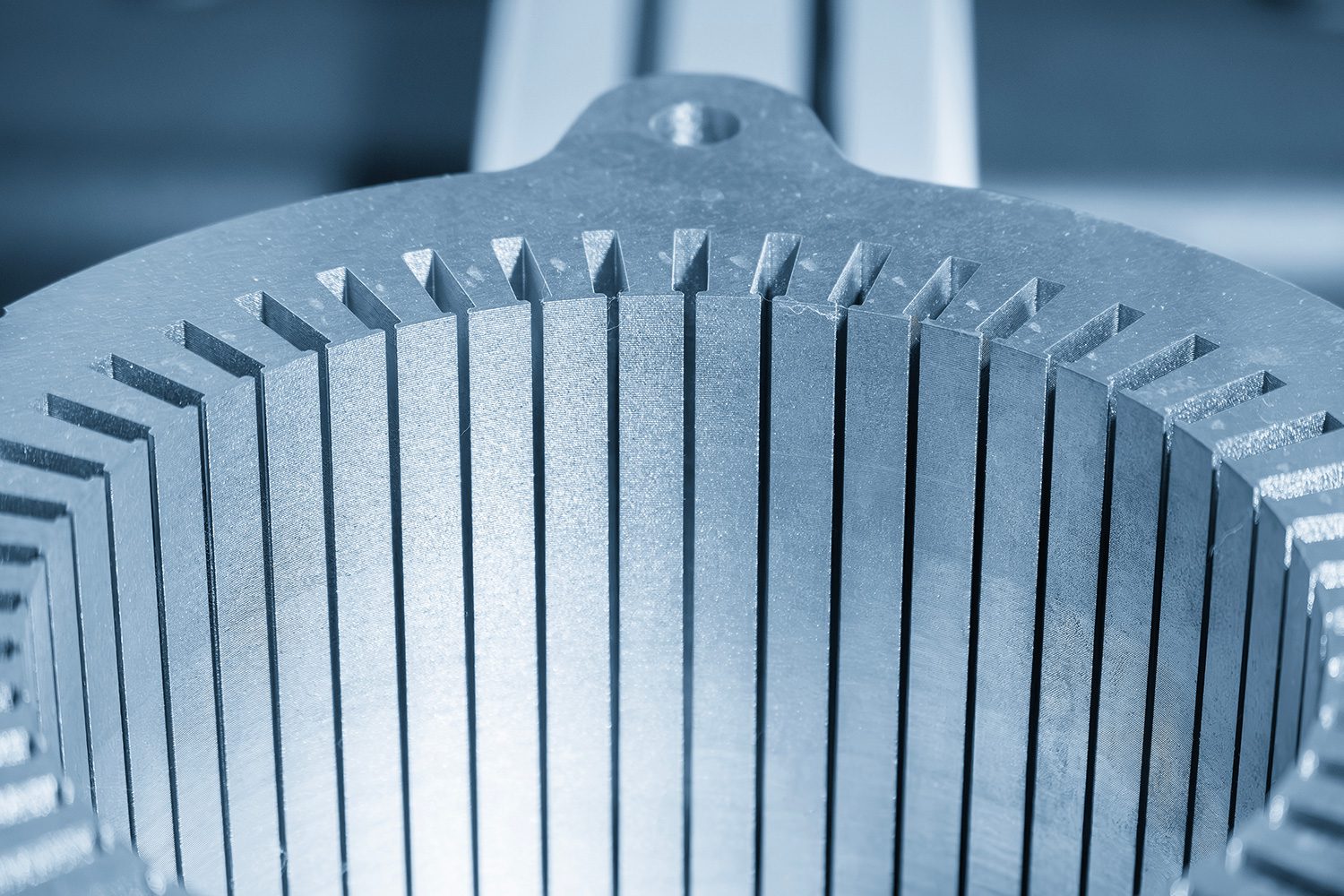
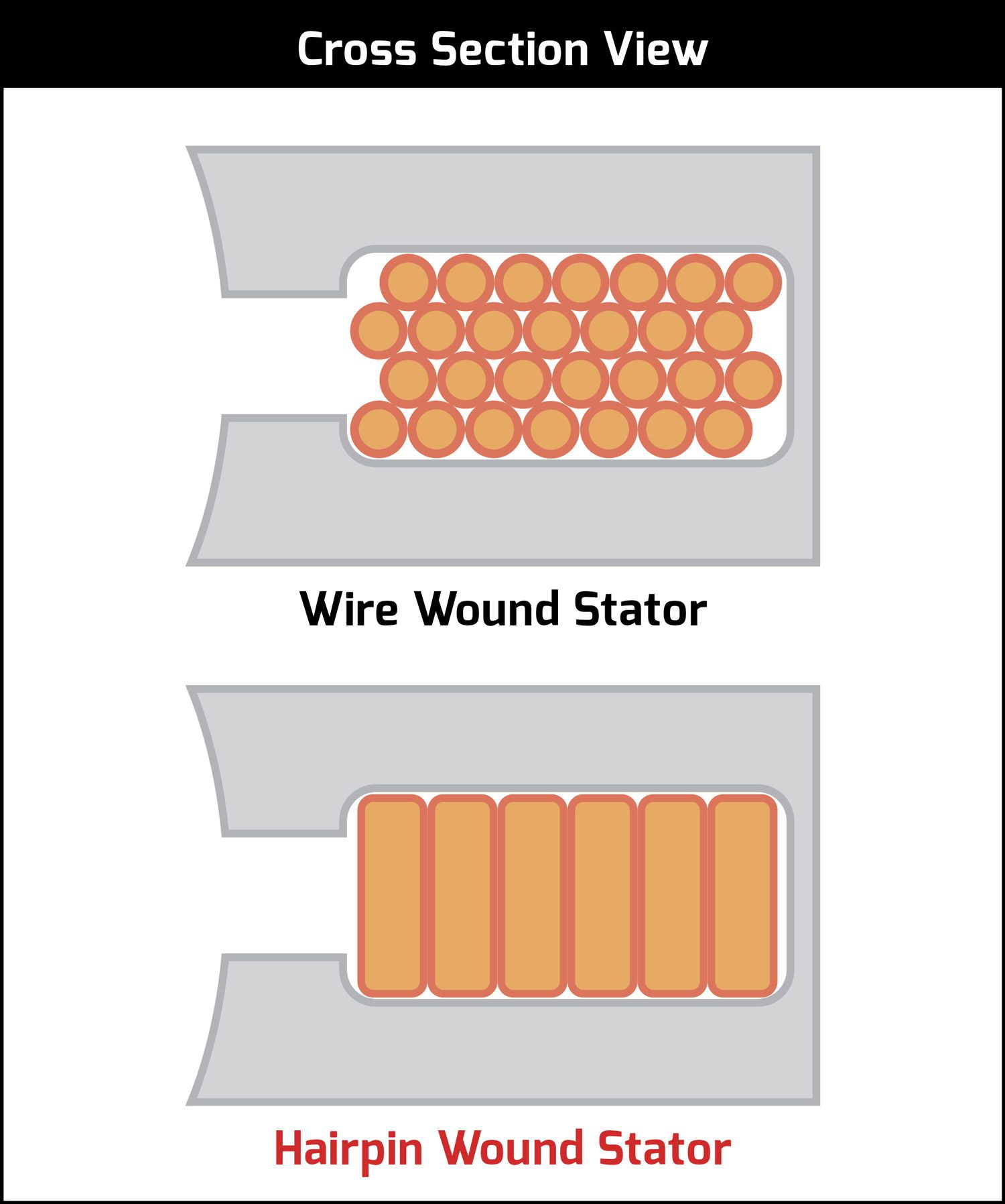
One major downside, however, is the relatively poor ratio of conductor area to slot area, or fill factor (typically 55%), especially when many turns are needed to achieve a given voltage rating, or many wires must be paralleled to reach a given ampacity, because each wire has an insulating coating which uses some proportion of the slot area. This issue can be ameliorated by using a single conductor—especially if it is square—that fills the entire slot width, but at some point the wire will be too difficult to wind—even into preformed coils for later insertion into the stator slots—without risk of damaging the insulation, and/or be too stiff to pack nicely inside the slot.
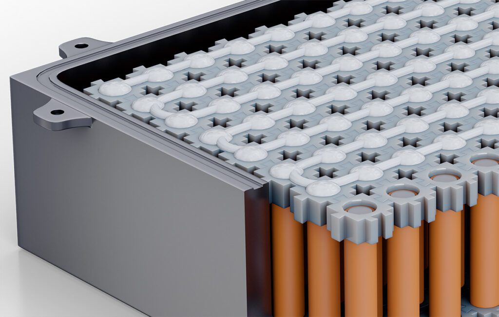
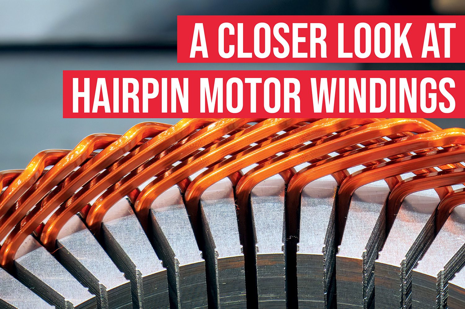
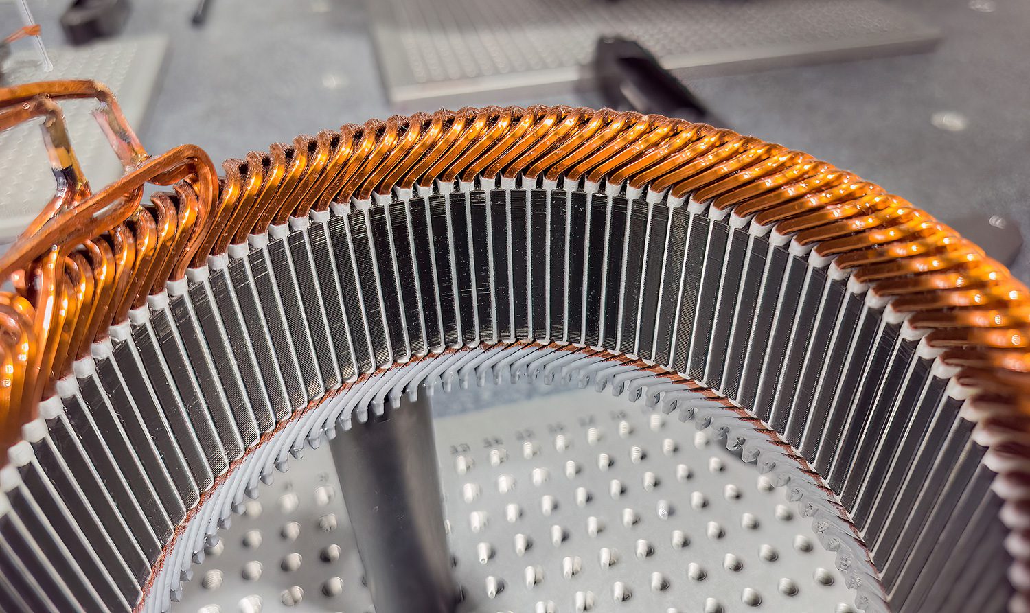
The hairpin winding sidesteps some of the issues that plague wire windings (while introducing others), as it is comprised of short copper segments that are formed into a shape that, well, resembles a hairpin.
At lower fundamental frequencies (i.e. RPM), such a large wire will also start suffering excessive losses from skin effect, which is the phenomenon that causes alternating current to penetrate less deeply into a conductor as frequency goes up, increasing its effective resistance. For example, the skin depth in copper at a reasonable maximum fundamental frequency of 400 Hz (or 12,000 RPM for a 4-pole motor) is 3.3 mm, which gives a wire diameter of 6.6 mm, roughly equivalent to #2 AWG. (A quick-n-dirty equation for the skin depth in mm for copper is 66 / (f^0.5).)
I’m about 99% certain that round magnet wire isn’t even made in such a large gauge (a quick check of the MWS website shows that #6 is their maximum—which is still pretty impressive!), but even if one goes with square wire (which is available in larger sizes), I doubt there is an automatic coil winding machine capable of handling it (and if there is, I really doubt you want to see its price).
Setting all that aside for the sake of argument, however, a 6.6 mm diameter wire has an ampacity of 137 A at a current density of 4 A / mm2 (which is ambitious, but not totally unreasonable), resulting in a maximum power rating for a 3-phase AC motor of approximately 95 kW, with a battery voltage of 400 VDC. Going with a 6.6 mm square wire boosts the ampacity to 174 A—because a round wire has 78.5% of the copper area of a square one (Pi / 4)—but the resulting ~121 kW still fails to impress. Thus, the EV traction motor using wire windings inevitably needs those windings to have many turns of many wires in parallel to end up in the sweet spot of battery voltage vs phase current vs total losses while still being cost-effective to manufacture.
They can be sized to fit precisely into each stator slot (or vice versa) to achieve a much higher packing factor (typically 70%) without undue risk of damage to the insulation during the insertion process.
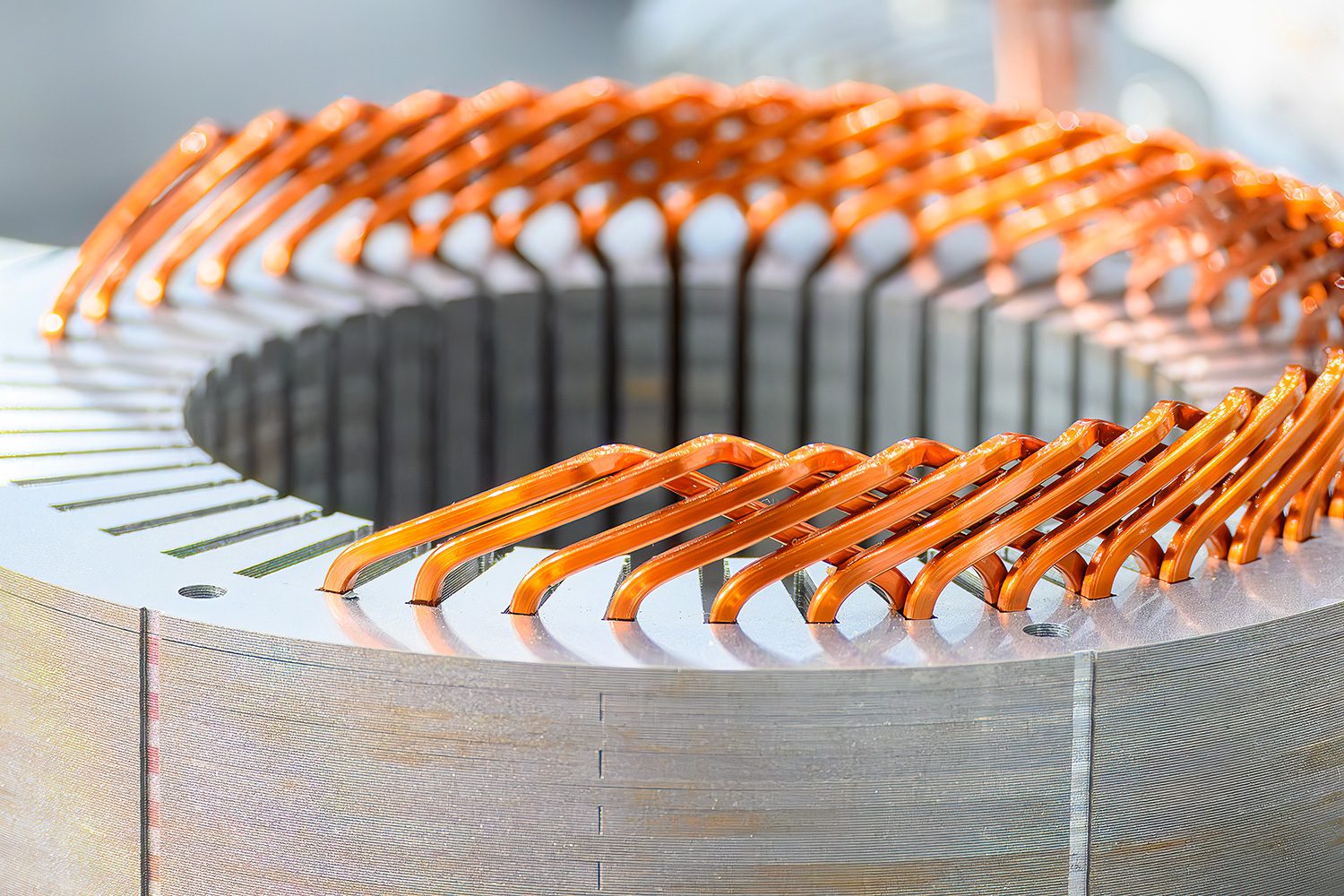
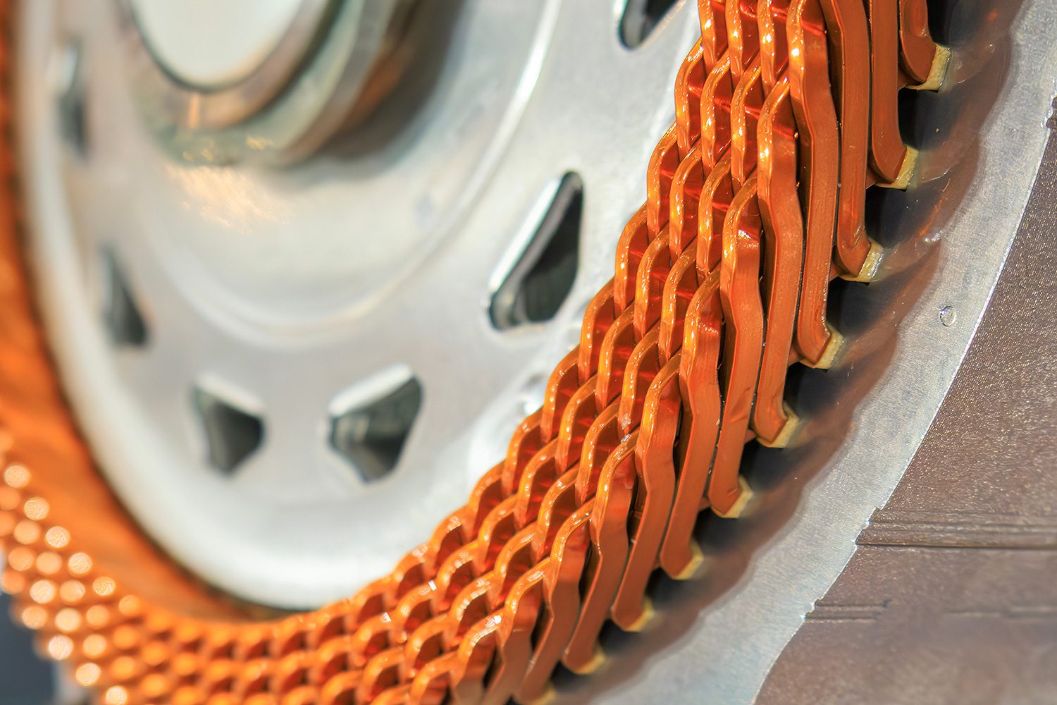
The hairpin winding sidesteps some of the above issues that plague wire windings (while introducing others), as it is comprised of short copper segments that are formed into a shape that, well, resembles a hairpin. These hairpin-like segments are then inserted into the stator slots directly and their ends bent so they can be welded one to the next to form a complete winding. It is also possible to preform wire windings into a squarish-shaped coil that can be directly pressed into its respective pair of slots, but even more slot area is required to avoid insulation damage, resulting in an even worse packing factor.
Basically then, hairpins being made from a single stout conductor is a benefit rather than a curse, and it also means they can be sized to fit precisely into each stator slot (or vice versa) to achieve a much higher packing factor (typically 70%) without undue risk of damage to the insulation during the insertion process. Skin effect still sets a limit on how thick each hairpin can be, but it is even possible to cheat this devil, somewhat, by making the hairpins rectangular in cross-section—another quick check of MWS shows that they can make rectangular magnet “wire” up to ~10 mm wide, for a total cross-section of 66 mm2, or nearly double that of a round 6.6 mm diameter wire.
Concentrated vs distributed windings
Another consideration is the question of how much torque ripple (i.e. vibration) a particular winding arrangement will produce, and the two choices here are “concentrated” or “distributed,” which more or less mean what they say. In a concentrated winding structure, there is one coil for each pole, for each phase (i.e. 6 coils in a 2-pole, 3-phase motor), whereas in a distributed winding structure each pole is split into several coils that overlap each other by one or more stator slots (sort of like slices of salami on a deli tray).
It is too difficult to bend the rather stout hairpins into the tight-radius turns that a concentrated winding requires, so a distributed structure it is.
Motors using a concentrated winding structure can be very compact for a given power out-put and are less expensive to manufacture, but suffer from high torque ripple and a trapezoidal back EMF waveform, which makes it harder for the inverter to control stator currents accurately and leads to higher losses in the entire inverter-motor circuit from harmonic heating. This structure is never used in EV traction applications (that I’m aware of, anyway).
Conversely, motors with a distributed winding structure have much smoother torque output, a sinusoidal back EMF waveform, and better loss distribution (though often with a higher total copper loss, because there is simply more copper). That said, it is too difficult to bend the rather stout hairpins into the tight-radius turns that a concentrated winding requires, so a distributed structure it is.
The hard part: joining all those hairpins
So far the hairpin winding construction sounds like an overall win, but—and there’s always a but—I’m betting some of you have already spotted a major downside, which is the sheer misery of how to join together many dozens—or perhaps many hundreds—of individual hairpins to create each motor winding coil. The usual first step—often done before the hairpins are inserted into the stator—is to strip the insulation from the ends so that each can be joined to the next one in the chain. Depending on the specific type of insulation, it can be removed with heat, a laser, a chemical or an abrasive. Heat-stripping is usually done by dipping the hairpin ends into a molten metal or salt bath, so it is quite possible to process many hairpins at once.
That said, there is always the risk that the insulation close to the stripped ends will be damaged by heat conduction, so allowance must be made for this (or plan on potting this end of the winding later on). Stripping with a laser minimizes this issue, and will work on just about any kind of insulation (and even clean the copper underneath), but it is obviously more expensive both in up-front capital and ongoing operational costs, and it is one of the slower methods, because each wire end has to be processed individually. A few types of magnet wire insulation can be chemically stripped, so can also be processed in batches, as with heat stripping, but with a similar caveat about damage to the insulation near the stripped ends. Finally, stripping with an abrasive—typically a sanding belt—seems to be most popular, as it works on every type of magnet wire insulation, like a laser, but the capital investment and operational costs are far lower. While each hairpin needs to be processed individually, the cycle time is a mere fraction of a second, so it’s fairly quick overall, and there is no risk of damage to the insulation beyond the stripped ends.
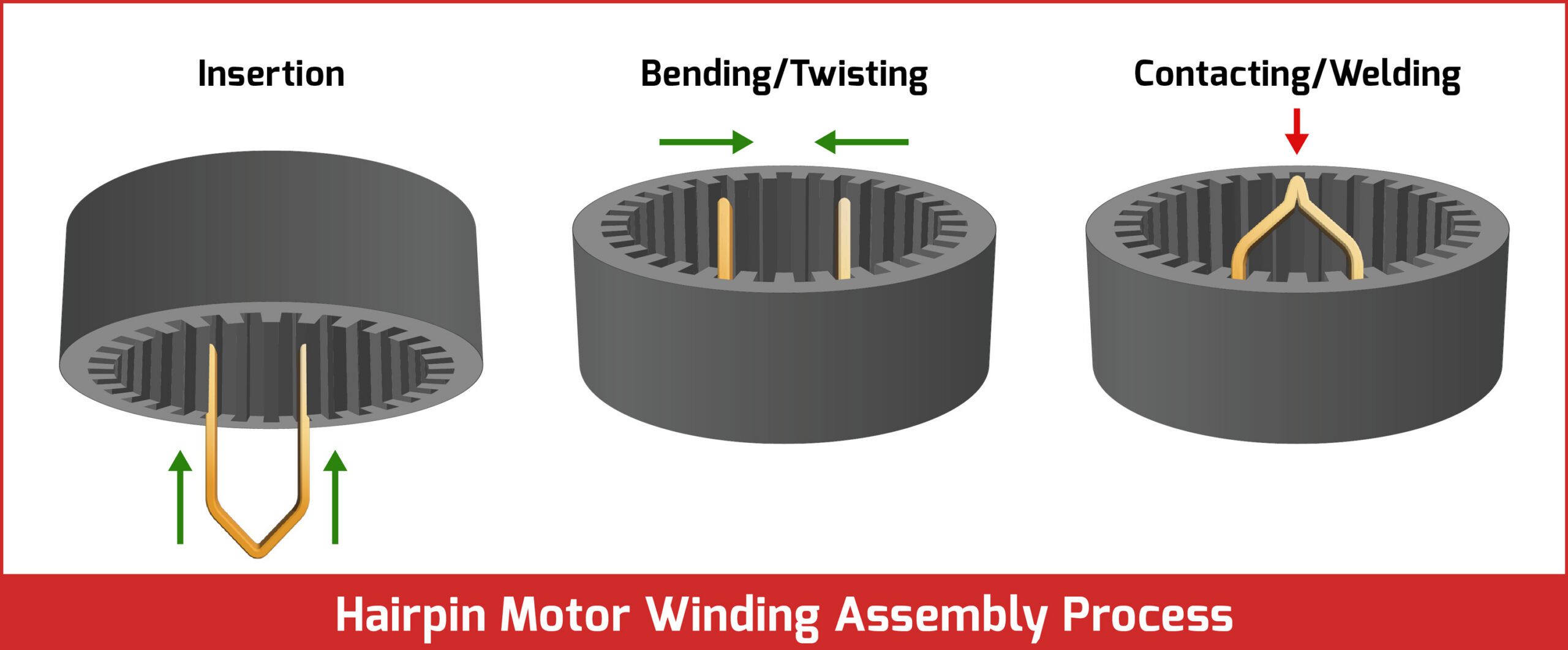
Inserting, bending and connecting the pins
After stripping, one or more hairpins are pressed into their respective pairs of (insulation-lined) slots in the stator (depending on how many turns each coil requires). The stripped ends are then bent to meet up with the next hairpin in the chain. This is fairly easy as long as the hairpin cross-sectional area vs bend angle is reasonable—needing to apply too much force is yet another risk factor for insulation damage, after all.
Once the ends have been bent to the correct angle, they are physically and electrically bonded together, either with soldering, brazing or welding. Soldering results in a relatively low-strength joint and requires the application of a flux that must subsequently be removed, so it’s not the best choice here. Brazing is basically a hotter version of soldering—flux and filler metal also required—but results in a much stronger joint (typically stronger than the base metal, in fact). Welding is by far the most popular method, and the simplest, least capital-intensive process is resistance welding (aka spot welding), in which the two hairpin ends are pressed together with considerable force by electrodes which send a huge pulse of current through them, causing them to fuse.
The main problem here is that copper is a very good conductor of heat and electricity, so it takes a massive current to spot weld it—easily into the kA or 10s of kA range for a weldment of this size. A more practical method is TIG (Tungsten Inert Gas) welding (or brazing) of just the top of the joint—this has been used to assemble conventional automotive alternators for many years now, so it has proven to be very reliable and cost-effective (though not necessarily the speediest method).
Finally, there is the moderately exotic method of laser welding (ignoring the really exotic method of electron beam welding) which can be very fast, is very easy to reposition to accommodate different designs, and produces a high-quality joint with low porosity, but which suffers from a high upfront capital cost and high operational costs (mainly due to the poor electrical efficiency of lasers and the fact that metals tend to be reflective). See the International Journal of the Society of Materials Engineering for Resources for a really good overview of laser welding hairpins.
The final step in the conventional hairpin assembly process is to re-insulate the welded ends and, optionally, potting such just to make extra-sure things don’t break apart at high speeds.
The next step: continuous hairpin windings
If this description of the hairpin stator manufacturing process still sounds devilishly complex to you—simplified and condensed as it is—well, you’re not alone, hence the feverish pursuit of what is variously referred to as a wave, or continuously formed (or flow) hairpin winding. Buzzword bingo aside, the basic premise is fairly easy to understand, which is to preform an entire coil (or even the entire winding structure) on a tapered mandrel (one reference refers to said mandrel as a “sword,” which I quite liked).
It does seem that the continuously formed process has an overwhelming advantage in assembly time and per-unit cost, so it is likely the way of the future.
The taper on the sword makes it easier to unload the preformed coil/winding onto a segmented belt that fixes each hairpin at the correct distance while is rolled into a cylinder on an arbor with fingers under each hairpin that can push them outwards. The arbor is then inserted into the stator so that its fingers are lined up with the stator slots, at which point the fingers are pushed out to press the hairpins into the slots. In theory, anyway—this is very much a “devil is in the details” kind of thing, and the whole continuously formed hairpin process is a radical departure from the conventional methods of hairpin winding manufacture, which itself is a radical departure from how a wire winding is typically manufactured.
While it is debatable which manufacturing method has the lower overall capital cost, it does seem that the continuously formed process has an overwhelming advantage in assembly time and per-unit cost, so it is likely the way of the future.
This article first appeared in Issue 75: January-March 2026 – Subscribe now.