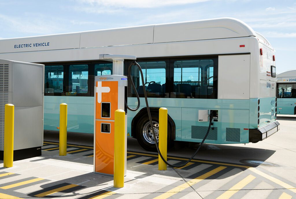
As far as we know, all EVs in production by major automakers use a conventional lead-acid battery for the 12 V system (surprising, but true – more on why in a bit) and this battery needs charging, just as it does in an ICE vehicle. While you could hang an alternator off the traction motor to keep the 12 V battery topped up and supply the average power demanded by the 12 V system, a more efficient (if not necessarily more cost-effective) solution is a transformer-isolated DC-DC converter between the traction and 12 V batteries.
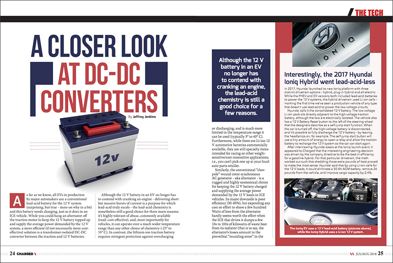
Interestingly, the 2017 Hyundai Ioniq Hybrid went lead-acid-less
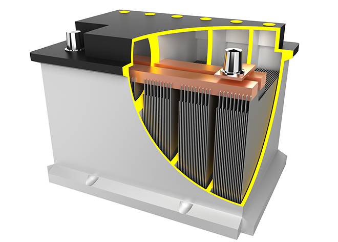
Although the 12 V battery in an EV no longer has to contend with cranking an engine – delivering short but massive bursts of current is a purpose for which lead-acid truly excels – the lead-acid chemistry is nonetheless still a good choice for three main reasons: it’s highly tolerant of abuse, commonly available (read: cost-effective), and, most importantly for vehicles, it can operate over a much wider temperature range than any other choice of chemistry (-25° to 55° C). In contrast, the lithium-ion traction battery requires stringent protection against overcharging or discharging, and is much more limited in the temperature range it can be used (typically 5° to 45° C). Furthermore, while there are Li-ion 12 V automotive batteries commercially available, they are still specialty items intended for racing or other weight-sensitive/cost-insensitive applications; i.e., you can’t pick one up at your local auto parts retailer.
Although the 12 V battery in an EV no longer has to contend with cranking an engine, the lead-acid chemistry is still a good choice for a few reaasons.
Similarly, the conventional “claw-pole” wound-rotor synchronous AC generator – aka alternator – is a rugged and highly economical choice for keeping the 12 V battery charged and supplying the average power demanded by the 12 V loads in ICE vehicles. Its major downside is poor efficiency (50-60%), but expending any cost or effort to shave a few hundred Watts of loss from the alternator hardly seems worth the effort when the ICE that drives it dumps a few 10s to 100s of kilowatts of waste heat from its radiator (that is to say, the alternator’s losses amount to the proverbial “rounding error” in the overall drivetrain losses of an ICE). The same is not true in an EV, however, as the energy efficiency of its electrical drivetrain (battery, inverter, and motor) can reach 85%, so a few hundred Watts of extra loss would add significantly to the total.
Given that EVs still use a lead-acid battery for the 12 V system, and that a DC-DC converter is the preferred means of keeping that battery charged, the next step is to define a functional specification for the latter. This tends to be the point at which many EV and Tier 1 OEMs sever any ties with practicality: a DC-DC converter costs a lot more than an alternator on a dollar-per-Watt basis, yet many of them are far more powerful and complicated than necessary (in stark contrast to the humble alternator, which is an excellent example of “value engineering”). For example, many DC-DC converters designed for EVs are bidirectional; that is, energy can also be transferred from the 12 V battery to the traction battery, not just the other way around. There is no practical scenario in which this makes sense, as the 12 V battery is typically sized to store around 300-600 Watt-hours of energy, and must supply many parasitic/standby loads when the EV is off, whereas the traction battery typically stores several 10s of kW-hrs, and the only parasitic loads when the EV is off (and not charging, of course) are from the battery management system and, if necessary, the temperature control system. Furthermore, all Li-ion chemistries exhibit much less self-discharge than lead-acid, so if any battery is going to die if the EV is left off the charger for too long it is the 12 V one.
Another specification which often lives up to the old saw, “nothing succeeds like excess,” is the output power rating. There are commercially available DC-DC converters from Tier 1 OEMs rated for 2.2 kW, or ~160 A at 13.8 V. The 2016 Model S DC-DC converter is rated for 2.5 kW (~180 A at 13.8 V), and even the 2016 Nissan Leaf gets a 135 A converter. Compare that to the 160 A alternator for a 2016 Cadillac Escalade with every power option imaginable (and a replacement is available from many auto-parts retailers for just $170 + core charge)! One would hope that all EV OEMs actually measure the peak and average current demand on the 12 V system of each of their models to size the DC-DC converter, but it is still difficult to believe this demand would exceed that of an ICE vehicle; after all, many of the more power-hungry accessories (power steering, air-conditioning, etc.) can be powered directly from an EV’s traction battery.
Lead-acid batteries tend to last longest when the depth of discharge is moderate (no more than 50%) and a so-called “3-stage” charge cycle is used.
The last specification that is important is the charging methodology, or algorithm. Lead-acid batteries tend to last longest when the depth of discharge is moderate (no more than 50%) and a so-called “3-stage” charge cycle is used: the bulk phase runs at a constant current to bring the battery up to 80% State of Charge; the absorption phase holds the voltage constant while current tapers to bring the battery up to near 100% SoC; the float phase reduces the voltage somewhat from the absorption phase just to counteract self-discharge. There should also be a slight temperature dependence to the absorption and float voltages of approximately -5 mV/° C / cell (which works out to -30 mV/° C for a 12 V battery).
There are many topologies that can be employed in an EV’s DC-DC converter, but only a few are truly practical, and the configuration/complexity of the secondary side, in particular, depends greatly on the current rating and, of course, on whether the converter needs to operate bidirectionally. Generally speaking, at this power level and input voltage range (200-600 VDC) the classic 4-switch full (or “H”) bridge is a safe choice for the primary side circuit, whether a phase-shift or duty-cycle modulation scheme is used. If there is an input filter capacitor before the switches, then the bridge is voltage-sourced. This configuration is less tolerant of any ripple current that might be generated by the main traction inverter, something which can be a significant problem in EVs. There also must not be any overlap in the on time of each bridge leg (that is, there needs to be some “dead time” each half cycle).
There are many topologies that can be employed in an EV’s DC-DC converter, but only a few are truly practical, and the configuration/complexity of the secondary side depends greatly on the current rating
The current-fed version replaces the shunt input capacitor with a series choke, so the switches are fed by a high-impedance current source. This makes the bridge highly tolerant of output shorts and any ripple current on the DC bus – both highly desirable attributes in this application – but the on times of each leg of the current-fed bridge must overlap, otherwise the switches will be destroyed (if you interrupt the flow of current through a choke it will create whatever voltage is necessary – i.e., arc – in order to maintain said flow). Unfortunately, this seemingly minor detail means that none of the most popular switching power supply control ICs can be used, because they enforce a minimum amount of dead time between the opposing switches; they are geared towards voltage-source topologies, in other words. Consequently, current-fed converters tend to require much more design effort to get working and to debug, so despite their advantages, they are less often chosen.
As for the secondary side, if the converter needs to operate bidirectionally, then a full bridge of active switches, rather than passive diodes, will be required. This reversal of the energy flow also inverts the operation of the converter – that is to say, if the converter is a voltage-fed bridge in the forward direction, it will be a current-fed bridge in the reverse direction, because the output choke of the voltage-fed bridge becomes the input choke of the current-fed bridge (see Figure 1).
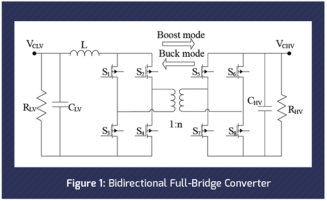
As might be inferred from the above explanation of the different timing requirements for the switches in voltage-fed vs current-fed bridges, this rather complicates the control of the converter, and all but requires that it be implemented either in software (with a microcontroller or DSP), with some rather kludgy custom hardware (e.g., logic gates), or with a relatively expensive Field-Programmable Gate Array (FPGA). Another complication is that the transfer function of the two converters – how output voltage relates to switch duty cycle, basically – is very different in voltage-fed (buck) mode and current-fed (boost) mode. The relationship of output voltage to switch duty cycle, while input voltage and load current are constant, is a linear and intrinsically stable function for the buck converter. In contrast, output voltage rises at an increasingly rapid rate with duty cycle in a boost converter (approaching infinity as duty cycle tends towards 100%), and it is also intrinsically unstable due to the presence of the infamous (to engineers, anyway) Right Half Plane Zero, in which any increase in duty cycle when in continuous conduction mode initially causes a decrease in output voltage, because current is only delivered to the output when the switch is off in boost-derived converters. In fact, pretty much everything is a massive headache when bidirectional operation is required, and a severe reduction in reliability is unavoidable as well, so there had better be an extremely good reason for going that route.
Everything is a massive headache when bidirectional operation is required, and a severe reduction in reliability is unavoidable as well, so there had better be an extremely good reason for going that route.
Synchronous rectification is one application for controlled switches on the secondary side of the DC-DC converter that is worth the headache. In a synchronous rectifier, MOSFETs, specifically, replace the passive diodes in the usual bridge rectifier because they can conduct current in either direction and act like a very low value resistance when turned on. In the simplest synchronous rectification scheme, the SR MOSFETs are switched on and off when passive diodes would naturally switch, which might seem pointless at first, but the advantage is that the voltage drop across a properly selected MOSFET will be much lower than even that of a Schottky barrier diode. For example, a typical Schottky diode rated for 30 V will have a voltage drop of around 0.6 V at rated forward current, while a typical 30 V MOSFET with appropriate current rating will exhibit a resistance of around 1 mΩ when turned on, resulting in a drop of just 0.05 V at 50 A (a practical upper limit for current through each board-mounted semiconductor device). Since there are two switches in series in a full-bridge, a rectifier comprised of Schottky diodes will drop 1.2 V, for an immediate 10-point hit to efficiency on a 12 V output (and will require getting rid of 60 W of waste heat at 50 A). In contrast, a bridge rectifier comprised of 1 mΩ MOSFETs will drop 0.1 V at 50 A, subtracting just 1 point from efficiency, and generating a mere 5 W of waste heat.
DC-DC converters for OEM EVs have a long way to go before they approach the economy/value of their electromechanical counterparts (or even their mains-supplied counterparts).
As of now, all DC-DC converters for OEM EVs have a long way to go before they approach the economy/value of their electromechanical counterparts (or even their mains-supplied counterparts). They are too powerful, too complicated and not nearly as reliable as alternators. That said, it took many years before all the kinks were worked out of alternators, too; the early units had plenty of problems with their field control regulators and rectifiers, in particular. In the meantime, the best way to encourage more progress in EV technology is to keep buying and driving them.
Interestingly, the 2017 Hyundai Ioniq Hybrid went lead-acid-less
In 2017, Hyundai launched its new Ioniq platform with three distinct drivetrain options – hybrid, plug-in hybrid and all-electric. While the PHEV and EV versions both included lead-acid batteries to power the 12 V systems, the hybrid drivetrain used Li-ion cells – marking the first time we’ve seen a production vehicle of any type that doesn’t use lead-acid to power the low-voltage circuits.
Hyundai calls it the consolidated 12 V battery. The low-voltage Li-ion pack sits directly adjacent to the high-voltage traction battery, although the two are electrically isolated. The vehicle also has a 12 V Battery Reset button to the left of the steering wheel that the designers describe as a self-jump start function. When the car is turned off, the high-voltage battery is disconnected, and it’s possible to fully discharge the 12 V battery – by leaving the headlamps on, for example. The self-jump start button will use a tiny amount of energy to open a relay and allow the traction battery to recharge the 12 V system so the car can start again.
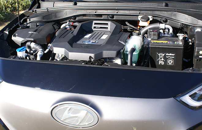
The Ioniq EV uses a 12 V lead-acid battery (pictured above), while the Ioniq Hybrid uses a Li-ion 12 V system.
After interviewing Hyundai execs at the Ioniq launch event, it appeared to Charged that the interesting engineering decision was driven by the company directive to be the best in efficiency for a gasoline hybrid. For that particular drivetrain, the math worked out such that shedding those extra pounds of lead proved to make the most sense. Hyundai said that by using Li-ion cells for the 12 V loads, it could eliminate a 50 Ah AGM battery, remove 26 pounds from the vehicle, and improve cargo capacity by 2.4%.
Read more EV Tech Explained articles.
This article originally appeared in Charged Issue 38 – July/August 2018 – Subscribe now.