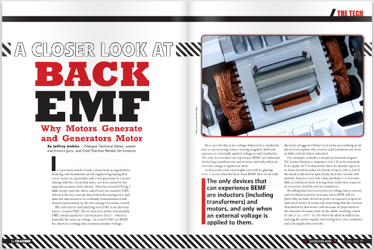
Why motors generate and generators motor
In a previous article I took a closer look at regenerative braking, and mentioned an old engineering saying that every motor is a generator and every generator is a motor (along with the caveat that some are more suited to the opposite purpose than others). This time around I’ll dig a little deeper into the effect called back (or counter) EMF, which is the key concept that makes this saying true, and also one that seems to be endlessly misunderstood and abused (particularly by the free energy/overunity crowd).
The first clue to demystifying back EMF is its alternate name, counter EMF. The second is to define and simplify EMF, which stands for “electromotive force” – which is basically the same as voltage1. So a back EMF (or BEMF for short) is a voltage that counters another voltage.
More specifically, it is a voltage induced in a conductor that is experiencing a time-varying magnetic field and opposes an externally applied voltage to said conductor. The only devices that can experience BEMF are inductors (including transformers) and motors, and only when an external voltage is applied to them.
At this point, your eyes might very well be glazing over…I mean, what the heck does BEMF have to do with the price of eggs in China? As it turns out, nothing at all, but it does explain why motors (and transformers) draw so little current when unloaded.
For example, consider a simple permanent magnet DC motor that has a resistance of 0.1 Ω at its terminals. If we apply 10 V to this motor then we should expect it to draw an initial pulse of current of up to 100 A, but if the shaft is allowed to spin freely, then the current will quickly drop to a very low value (perhaps 1 A) because little mechanical work is being done (only that required to overcome friction and air resistance).
Recalling that electrical power is voltage times current and mechanical power is torque times RPM will explain why so little electrical power is required to spin an unloaded motor. It is also not surprising that the current demanded by this motor will increase in proportion to the amount of torque load on the shaft, reaching a limit of 100 A (i.e. 10 V / 0.1 Ω) when the shaft is stalled (assuming the power supply and wiring have zero resistance and can supply this current).
What is not clear from mere observation is why the motor only draws the electrical power necessary to deliver the mechanical power demanded of it (plus inevitable losses). It’s not because the resistance of the motor changes – though it will tend to increase as it gets hotter – rather, it’s because the conductors in the armature are moving past a stationary magnetic field provided by the permanent magnets, and therefore a voltage is induced in them that opposes the applied voltage, that is: BEMF. This induced voltage is proportional to the intensity of the magnetic field, its rate of change (as experienced by the wires as they move past the pole pieces), and the number of turns of the wire.
The polarity of the induced voltage (BEMF) is the opposite of the applied voltage, so it reduces the “actual” voltage experienced by the armature turns, which reduces the amount of current flowing through the motor. This explains why an unloaded motor draws little current, and why a stalled motor draws maximum current, but why does a moderately loaded motor draw a moderate current? In a nutshell, it is because whenever a current flows through a wire it creates a magnetic field2. Thus, as our example motor is more heavily loaded, it slows down just a bit, which reduces the BEMF and lets more current flow. This current then opposes the static field of the permanent magnets more strongly until a new equilibrium is reached (note that this is why you must be very careful about overloading motors with permanent magnet fields – too much current through them and you will demagnetize the magnets).
While it is easy to imagine the creation of BEMF in motors that use permanent magnets for the field (such as the aforementioned permanent magnet DC motor, or the AC variants that are popular in OEM electric vehicles), all motors exhibit this phenomenon. The only difference is that the BEMF waveform will mimic that of the motor type. That is to say, a permanent magnet DC motor will produce DC BEMF, an AC induction motor will produce sinusoidal BEMF, and PM AC motor types will produce either sinusoidal or trapezoidal BEMF, depending on the distribution of windings in the armature3.
This is true even with modern drives that use pulse width modulation, or PWM, to control the speed and/or torque of a motor. A PWM drive chops a DC supply voltage into discrete pulses whose average value must be less than or equal to the supply (minus a volt or two in on-state drop in the switches). Thus, in a DC drive the average voltage supplied to the motor can vary from 0 V up to just under the supply voltage. How does this affect the BEMF waveform in, say, an induction motor? As long as the PWM frequency is high enough (and/or the inertia of the load is high enough) the average voltage will cause an average current to flow. This average current will result in an average torque, which, working against the resistance of the load, will result in an average speed. I keep repeating the word “average” to drive home the point that the shaft of the motor is turning continuously, not “stepping” a discrete angular amount each time the PWMed output is on, and pausing each time the output is off (like a stepper motor). As long as the shaft turns smoothly (either because of high inertia, high PWM frequency or both), the BEMF waveform will look the same as if the motor were supplied by a battery with the same voltage as the averaged output of the drive.
The same happens in an AC motor, except, of course, the ratio of on time to off time is varied to create a sinusoidal average voltage, and therefore a sinusoidal average current. The BEMF waveform will also be sinusoidal, subject to the same requirement that the PWM frequency and/or load inertia be high enough that the torque is essentially ripple-free. So BEMF is what limits the current through a motor whenever the shaft is not stalled, and it explains why the current drawn by a motor is proportional to load and not just the applied voltage divided by the resistance. BEMF can also be used for “sensorless” speed control, with the caveat that some types of motors – e.g. brushed DC and trapezoidal PMAC – are more amenable to this than others. BEMF cannot do useful work in and of itself, however, so no free lunches here, and no need for any tinfoil hats!
Footnotes
1 For the sticklers for detail, an EMF is more properly defined as a generated potential difference generated voltage, i.e., that produced by a battery, photovoltaic cell, generator, etc. – as compared to a voltage drop across a resistance.
2 Lenz’s Law
3 Yes, AC motors have “armatures” – this is just the part of the motor that experiences a time-varying magnetic field, rather than the part that supplies the fixed field (which is, rather unimaginatively, called the field).
Jeffrey Jenkins is Technical Editor at Charged, a power electronics guru, and the Chief Electron Herder for Evnetics.
Read more EV Tech Explained articles.
This article originally appeared in Charged Issue 9 – AUG 2013 – Subscribe Here.