


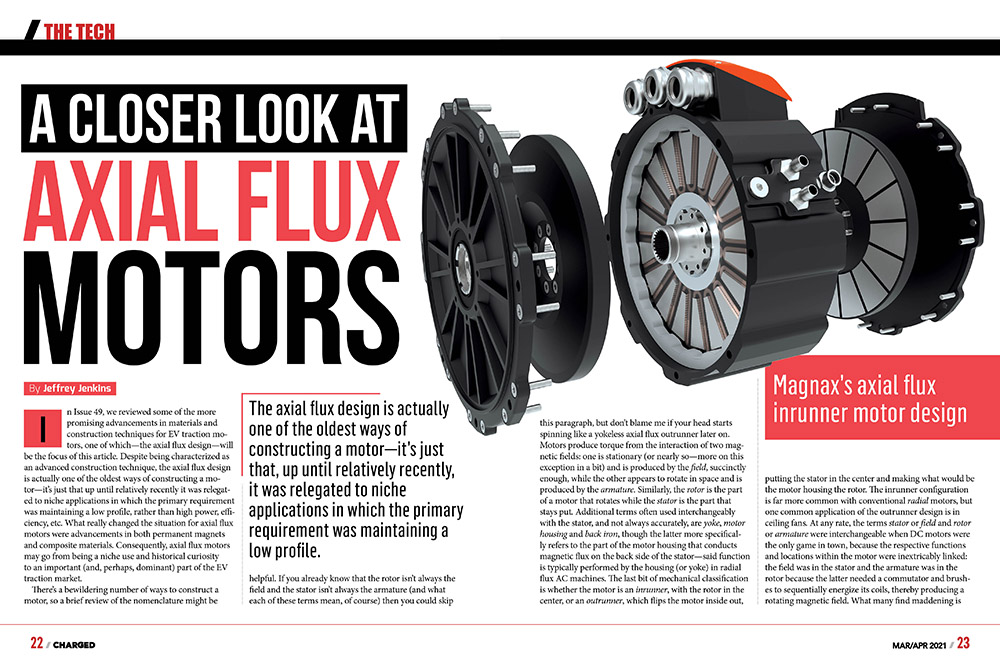
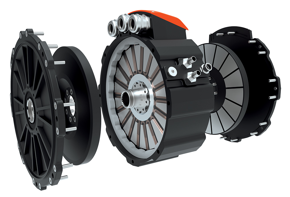
In Issue 49, we reviewed some of the more promising advancements in materials and construction techniques for EV traction motors, one of which—the axial flux design—will be the focus of this article. Despite being characterized as an advanced construction technique, the axial flux design is actually one of the oldest ways of constructing a motor—it’s just that up until relatively recently it was relegated to niche applications in which the primary requirement was maintaining a low profile, rather than high power, efficiency, etc. What really changed the situation for axial flux motors were advancements in both permanent magnets and composite materials. Consequently, axial flux motors may go from being a niche use and historical curiosity to an important (and, perhaps, dominant) part of the EV traction market.
The axial flux design is actually one of the oldest ways of constructing a motor—it’s just that, up until relatively recently, it was relegated to niche applications in which the primary requirement was maintaining a low profile.
There’s a bewildering number of ways to construct a motor, so a brief review of the nomenclature might be helpful. If you already know that the rotor isn’t always the field and the stator isn’t always the armature (and what each of these terms mean, of course) then you could skip this paragraph, but don’t blame me if your head starts spinning like a yokeless axial flux outrunner later on. Motors produce torque from the interaction of two magnetic fields: one is stationary (or nearly so—more on this exception in a bit) and is produced by the field, succinctly enough, while the other appears to rotate in space and is produced by the armature.
Similarly, the rotor is the part of a motor that rotates while the stator is the part that stays put. Additional terms often used interchangeably with the stator, and not always accurately, are yoke, motor housing and back iron, though the latter more specifically refers to the part of the motor housing that conducts magnetic flux on the back side of the stator—said function is typically performed by the housing (or yoke) in radial flux AC machines.
The last bit of mechanical classification is whether the motor is an inrunner, with the rotor in the center, or an outrunner, which flips the motor inside out, putting the stator in the center and making what would be the motor housing the rotor. The inrunner configuration is far more common with conventional radial motors, but one common application of the outrunner design is in ceiling fans. At any rate, the terms stator or field and rotor or armature were interchangeable when DC motors were the only game in town, because the respective functions and locations within the motor were inextricably linked: the field was in the stator and the armature was in the rotor because the latter needed a commutator and brushes to sequentially energize its coils, thereby producing a rotating magnetic field.
What many find maddening is that this relationship is pretty much always reversed in the AC motor: the stator consists of an array of coils that are sequentially energized by phase-shifting the currents flowing through each of them (via the inverter, in an EV), rather than mechanically switching from one coil to the next with a commutator. The field in an AC motor must be located in the rotor, then, and it can either be directly supplied by permanent magnets (or even an electromagnet fed by brushes and slip rings), or indirectly supplied by the stator coils through transformer action, or induction. The latter approach is the basis of the AC induction motor, or ACIM, and it is also the exception mentioned above to the field always being stationary in space. This is because current can only be induced into the rotor if there is a relative difference in the speed of its rotation with respect to the apparently rotating magnetic field from the stator/armature. The bigger the difference in speed, or slip, the stronger the current induced into the rotor will be, and the more torque will be available…up until a point, that is, beyond which the motor stalls and the rotor quickly overheats (the rotor in an induction machine is essentially a short circuit on the secondary of a very high step-down ratio transformer).
Note that there is not a topological continuum between the two constructions, they really are fundamentally different ways of making a motor.
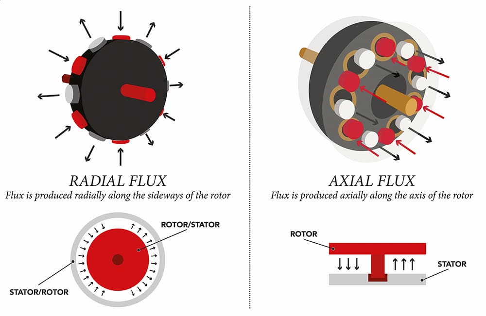
With the nomenclature out of the way, it’s time to dive right into the axial flux construction itself, and how it differs from the conventional radial flux construction. The figure above compares the two approaches schematically, with the radial flux construction consisting of a smaller cylinder nested within a large one, while the axial flux construction consists of a central disk sandwiched between two others, all of similar diameter.
The key difference is that the magnetic flux travels along radial lines in the radial flux machine and…no prizes for guessing correctly…along axial (or azimuthal) lines in the axial flux machine. Note that there is not a topological continuum between the two constructions; merely shortening the length of the rotor until it becomes a disk won’t turn a radial flux machine into an axial flux one, so they really are fundamentally different ways of making a motor. And as is usually the case in engineering, one type of motor is not unequivocally superior to another.
Despite being totally different ways of constructing a motor, there are axial flux versions of every radial flux machine, though some types are more suitable than others for each design. As mentioned above, the outrunner configuration is relatively rare in the radial flux design, but has some compelling advantages in the axial flux configuration. Conversely, the majority of radial flux machines are the asynchronous induction type, whereas most axial flux machines are the PM synchronous type. The reasons for these lopsided distributions will become apparent as the various ways of constructing an axial flux motor are discussed below.
The rotor in an inrunner axial flux motor has a tough life, as it must withstand considerable shear force radially as RPM increases, as well as alternating torsional forces axially, which are proportional to torque.
With the inrunner configuration of an axial flux PM synchronous motor, the central disk rotor contains permanent magnets whose poles alternate (i.e. North-South-North-South), while the stator is split into the two discs sandwiching the rotor. The rotor in an inrunner axial flux motor has a tough life, as it must withstand considerable shear force radially as RPM increases (more informally known as centrifugal force), as well as alternating torsional forces axially, which are proportional to torque. Furthermore, any part of the rotor disk that might be subjected to the magnetic fields from the stator/armature coils (aside from the field magnets themselves) must be electrically non-conductive (and non-magnetic) to avoid losses from eddy current induction.
One potential solution is to make the inner part of the rotor—which isn’t in the pathway of the stator electromagnets—out of, say, aluminum, with wedge-shaped magnets glued along its outside perimeter so that the magnets fit together side by side with little or no gap between them, and, finally, a few wraps of banding to keep the magnets from flying off. Since the maximum torque of a PM machine is proportional to the field strength of its magnets, as well as their resistance to demagnetization (i.e. the energy product), that all but demands that the magnets be of the rare earth type (e.g. neodymium-iron-boron, NdFeB, or samarium-cobalt, SmCo). Unfortunately, rare earth magnets tend to have relatively poor mechanical properties (only ferrite, aka ceramic, magnets are more fragile), and relying on edge-gluing between magnets to resist the torsional forces from torque production is just asking for trouble.
Consequently, the inrunner rotor typically consists of a frame to hold the (still wedge-shaped) magnets, and this frame necessarily takes up some of the volume that would otherwise be capable of torque production, so volumetric efficiency suffers. The parts of the rotor frame between each magnet will also be exposed to the alternating fields from the stator coils, so the frame must also be magnetically inert. The combination of needing high strength in the smallest amount of volume possible while also being non-conductive/non-magnetic means that the rotor frame all but has to be constructed out of composite materials such as glass or carbon fiber and epoxy.
Needless to say, the combination of rare earth magnets and a carbon fiber composite frame to hold them does not make for a cheap rotor assembly. Furthermore, the stator for the inrunner design requires distributed, overlapped windings, rather than simple concentrated coils, and “back iron” (or a yoke) to complete the magnetic circuits on each side of the rotor, meaning that the stator isn’t all that cheap to make either. On the plus side, considerable weight/volume is saved in the stator, as a conventional yoke/housing isn’t needed, and some cooling of the stator—which is where most of the losses occur in any AC motor—by natural convection is possible. However, at the power (and density) levels needed in an EV, liquid cooling is pretty much mandatory, so chalk this one up as more of a wash.
The outrunner (internal stator) configuration of an axial flux PM synchronous motor splits the PM-field rotor into two halves, while the stator/armature is in the center. This seemingly minor inversion of where the stator/armature and rotor/field are located in the motor has effects both subtle and profound on everything from the manufacturability of the motor to how it performs at high torque vs high RPM.
One major advantage over the inrunner configuration is that the stator coils can be of the concentrated winding type, rather than spanning across multiple slots (distributed type), and the magnetic flux flows in a straight line through each stator coil, so grain-oriented steel can be used for that oh-so-sweet +2 points or so of efficiency gain. A difference that could be advantageous or not, depending on the application needs, is that there needs to be a back iron pathway on the side of the magnets facing away from the stator/armature pole faces. This can be accomplished by forming the magnets into shallow “C” shapes so they can be mounted onto a lightweight aluminum or even composite disk—very pricey—or else by using a steel disk as both mounting surface and back iron so that flat magnets can be used; this option costs a lot less at the expense of a having a lot more rotating mass.
In the toss-up category, the internal stator in outrunner axial flux machines does not appear to be any more difficult to liquid-cool than the external stator in inrunners (that said, one inrunner axial motor manufacturer, Magnax, argues otherwise), and while rigidly securing the stator to a mounting surface requires a bit more lateral thinking, it’s also not really any more difficult than it is for a conventional inrunner design (though it does generally mean adding a housing—something which will be needed anyway, to shield the spinning rotors).
It’s also possible to make an axial flux induction motor (AFIM), in either the inrunner or outrunner configuration, but they are still relatively rare.
It’s also possible to make an axial flux induction motor (AFIM), in either the inrunner or outrunner configuration, but they are still relatively rare. One reason for this is that torque is proportional to the depth of the cast aluminum (or copper) shorting bars in the squirrel cage, and more depth is easy to come by in the radial flux machine’s relatively large-diameter cylindrical rotor as compared to the thin disk(s) of the axial flux machine. Still, there is always a tremendous incentive to replace expensive permanent magnets with cheap cast aluminum (or even cast copper), so expect a lot more development to occur in the AFIM space in the future.
Read more EV Tech Explained articles.
This article appeared in Charged Issue 54 – March/April 2021 – Subscribe now.