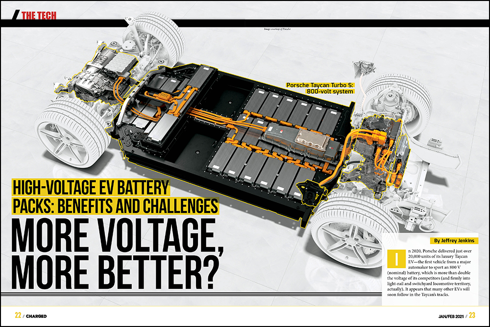
In 2020, Porsche delivered just over 20,000 units of its luxury Taycan EV—the first vehicle from a major automaker to sport an 800 V (nominal) battery, which is more than double the voltage of its competitors (and firmly into light-rail and switchyard locomotive territory, actually). It appears that many other EVs will soon follow in the Taycan’s tracks.
Delphi Technologies recently said it will supply 800 V inverters to three out of the top four global premium automakers in the next few years. Kia and Hyundai have both released details of upcoming 800 V architectures, and GM said that its 2022 Hummer EV will have the “unique ability to switch its battery pack from its native 400 V to 800 V for charging.”
GM said that its 2022 Hummer EV will have the “unique ability to switch its battery pack from its native 400 V to 800 V for charging.”
Whether this is just another case of specmanship or something more noteworthy is the subject of this article, but regardless, it also suggests that silicon carbide (SiC) technology is rapidly being adopted by the EV OEMs. This is because the only other type of semiconductor switch with sufficient VA rating for use in an EV traction inverter is the IGBT, and 1,200/1,700 V IGBTs are relatively slow devices, limiting the maximum practical PWM frequency to the single-digit kHz range if switching losses are to be kept acceptably low. Granted, this isn’t much of an issue for the traction inverter, since high-quality sinusoidal currents can be produced with relatively low PWM frequencies, but for the charger and any other power converters that operate at pack voltage, there is considerable motivation to push the switching frequency much higher, as that reduces the size (and cost) of both the magnetic components (transformers and inductors), as well as the energy storage capacitors (i.e. for the DC link, output filters, etc.).


As with most things in engineering, arbitrarily increasing the pack voltage isn’t unequivocally a good thing, and that’s even without invoking a reductio ad absurdum argument (e.g. if 1 kV is better than 100 V, then 10 kV is better than 1 kV, etc.). Still, there are some benefits to increasing the pack voltage, and the most obvious is that less cross-sectional area in copper will be needed to handle the same amount of power (offset by an increase in insulation thickness to withstand the higher voltage—but more on that later). Given that some DC fast chargers have actually resorted to liquid-cooling the charging cables to keep their temperature rise manageable, increasing the voltage to boost the power delivered rather than the current seems to be a far more reasonable solution, and even saves a percentage point or two in efficiency (from reduced I2R losses in the cable and charge port connectors).
Given that some DC fast chargers have actually resorted to liquid-cooling the charging cables to keep their temperature rise manageable, increasing the voltage to boost the power delivered seems to be a reasonable solution, and even saves a percentage point or two in efficiency.
A less obvious benefit of running a higher pack voltage, and one that is arguably more in the realm of the theoretical, is that traction motor RPM can be pushed higher without a loss of torque from field weakening. Of course, the No Free Lunches principle applies here too, as AC losses in the motor—both copper (i.e. the windings) and iron (i.e. the magnetic circuit)—increase with RPM, and in an exponential fashion (that is, to a power higher than one). There is also a mechanical limit to just how high you can push RPM before the rotor “rapidly self-disassembles.” Though, to be fair, torque is proportional to current, and the resistive losses of the windings are also exponentially proportional to current (i.e. from I2R again), so demanding more torque to get more power from a particular motor runs into the law of diminishing returns as well. This is why you can’t extract an arbitrarily high amount of power out of a given motor, and why the benefits of increased voltage or current in the same motor are perhaps more theoretical than actual. Still, most motors can tolerate downright astonishing overloads (3x-10x, depending on the type) for brief periods of time, an attribute that happens to be ideal for EV traction applications.
It might not seem that increasing the pack voltage would have much effect on the pack itself, but there are a few issues that need to be considered, the most obvious being that a higher voltage is more likely to cause electrocution should one find oneself inadvertently part of the battery circuit. Of similar concern is that higher voltages are also more likely to start an arc, and said arcs will require more separation distance before they are extinguished. This mainly affects the construction of any fuses in the battery circuit, because at low DC (<50 VDC) to moderate AC voltages (<150 VAC) a fuse can merely rely on the fusible link melting to open up a circuit, but at higher voltages, techniques to increase the separation distance and/or fill the gap with non-conductive materials to quench any arcs must be employed, all of which greatly increase the cost of the fuse. Another issue is that the capacity (in Ah) of a battery is only as good as its weakest cell, so the more cells in series, the greater the likely impact of the weakest one. This is less of an issue for packs comprised of many lower-capacity cells wired in parallel, first, then in series, rather than those comprised of single large format cells in series, but it’s still a consideration. The last issue pertaining to the pack here, and perhaps the most insidious and least obvious one, is that leakage currents flowing from battery to chassis to battery again increase with pack voltage. These leakage pathways are typically from condensation, but can also occur if electrolyte has escaped from a venting or ruptured cell, an altogether more serious situation in which, arguably, the leakage current would be the least of one’s worries. Regardless of the cause, any leakage current from pack to chassis can also result in current to ground (i.e. when the charger is connected) which can trip the usually-mandatory ground-fault circuit interrupter, disconnecting the charger from the pack. Needless to say, coming back to an EV that was plugged into a charger only to find no charging had occurred is unlikely to make a positive impression.
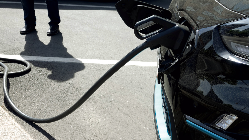
As hinted at above, another benefit of a higher pack voltage is a reduction in the size of the wires needed for the charging cable for a given power output (i.e. charging rate). This is not as inconsequential as it might seem at first glance, because the charging cable can be surprisingly heavy once you need to deliver more than about 125 A or so (i.e. the v1 CHAdeMO spec). Using a 350 kW DC fast charger as an example, charging a 350 V (nominal) pack would require 1,000 A, while an 800 V pack would drop that down to around 440 A. To carry 1 kA with an acceptable temperature rise would require wires of at least the 750 MCM size (750,000 circular mils, or 380 mm2 in area), each weighing about 3.7 kg / m (or 2.7 # / ft). A typical charging cable of 5 m length would end up weighing at least 37 kg (~81 #). Hence, going to the trouble of liquid-cooling the wire to get away with a smaller gauge starts to seem eminently reasonable. However, the 440 A needed to achieve the same power level with the 800 V pack could be delivered with 4/0 wires (about 107 mm2 in area) that weigh about 1.2 kg / m (or 0.82 # / ft) each, so a 5 m cable would then weigh about 12 kg (~27 #). Even a 12 kg / 27 # cable will be on the unwieldy side—a 37 kg / 81 # would be about as manageable as a live anaconda! Now it is true that the wires for the higher pack voltage cable will need to have thicker insulation—there is actually a step change in most safety agency requirements at 600 V, in fact—but the relative impact here is minuscule, as the insulation is typically just a few mm in thickness, and the materials used—PVC, EPDM, etc.—are about 1/8th the density of copper.
Where thicker insulation does have more of a negative impact is in the magnetic components (i.e. inductors, transformers and even motors), because an increase in insulation volume requires a concomitant decrease in magnetic material volume (and/or copper volume), and therefore a decrease in power handling capacity for said component. This is usually a minor effect, however, and oftentimes multiple layers of insulating coating (or builds in the argot) are applied to magnet wire, anyway, both because it results in a more reliable component and because it can sidestep the need for multiple layers of insulating tape between windings and/or between windings and core (again, the core here can be for an inductor, transformer, motor, etc.).
The first big change is that electrolytic capacitors might not be practical to use because 450 V is the highest working voltage that is commonly available.
Little change is required for the circuits used in the traction inverter, charger, or 12 V output DC/DC converter as a result of an increase in the pack voltage, but the component selection and some of the operating parameters (e.g. switching frequency) will definitely be affected, along with the same need for more distance between components at different potentials and/or thicker insulators. The first big change is that electrolytic capacitors might not be practical to use because 450 V is the highest working voltage that is commonly available. Sure, “elkos” can be wired in series to achieve a higher voltage rating, but because they tend to have rather high leakage currents, they also need rather low-value balancing resistors across each one to ensure voltage is split evenly among them (the rule of thumb is to set the balancing resistance to pass 10x the capacitor’s worst-case leakage current). Film and ceramic dielectric capacitors will typically prove to be better choices above 400 V or so, then, because both are available in >1 kV ratings, dielectric losses are much lower (especially for polypropylene film and NP0 ceramic) and these losses tend to be flatter over temperature (especially at the cold end), leakage currents are orders of magnitude lower, and, of course, there’s no electrolyte that can leak all over or simply dry out over time (leading to higher losses, causing more electrolyte to evaporate, and so on).
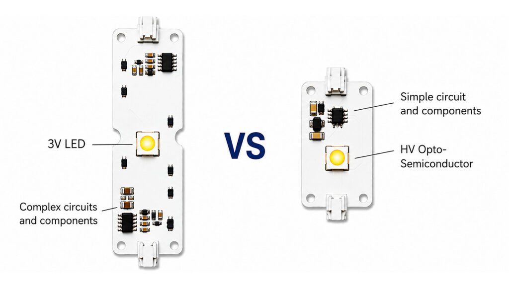
The optimal type of semiconductor switches and diodes to use at the 800 V pack level is a bit less clearly delineated, and the ultimate winner will depend heavily on the switching frequency, RMS current and precise application.
The optimal type of semiconductor switches and diodes to use at the 800 V pack level is a bit less clearly delineated compared to the choice of capacitor, and the ultimate winner will depend heavily on the switching frequency, RMS current, and, to a lesser extent, the precise application. In the inverter there is little need to push the switching frequency above the ultrasonic range because that won’t reduce the size of the “magnetics” (i.e. the motor), and there will always be some overlap of voltage and current during the transitions (i.e. “hard switching”). Furthermore, the stray currents—including the dreaded cause of EDM-like bearing damage—go up with switching frequency and/or pack voltage. In the other EV-related power converters—charger and DC/DC converter—there is far more flexibility in circuit topology, frequency, etc., so it is possible to employ circuit techniques that achieve soft-switching (aka “quasi-resonant”) or even fully-resonant operation, in which case the switching frequency is really only limited by the capabilities of the switches (and diodes). For SiC switches and diodes that limit is awfully high indeed, such that the dimensions of the specific package, board layout and other parasitics become the dominant factors (and complying with Electromagnetic Compatibility regulations…). All told, increasing pack voltage from 350 V to 800 V will likely prove to be more of an evolutionary step forward, rather than a revolutionary one, but it does seem like a logical progression overall.
Read more EV Tech Explained articles.
This article appeared in Charged Issue 53 – January/February 2021 – Subscribe now.