


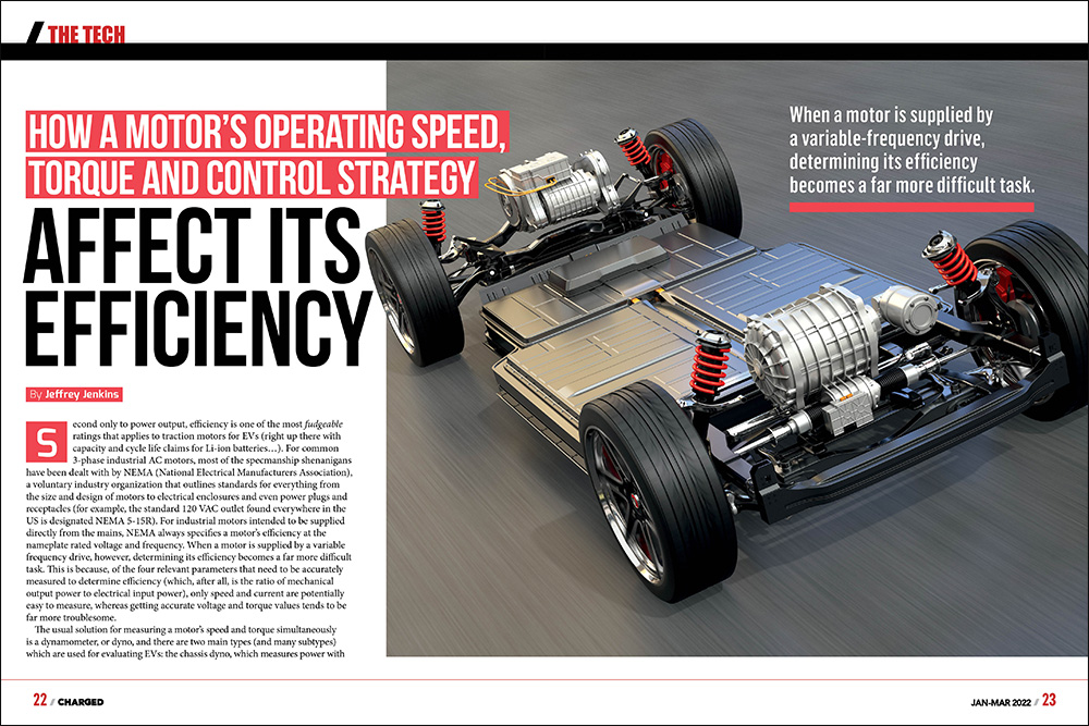
Second only to power output, efficiency is one of the most fudgeable ratings that applies to traction motors for EVs (right up there with capacity and cycle life claims for Li-ion batteries…). For common 3-phase industrial AC motors, most of the specmanship shenanigans have been dealt with by NEMA (National Electrical Manufacturers Association), a voluntary industry organization that outlines standards for everything from the size and design of motors to electrical enclosures and even power plugs and receptacles (for example, the standard 120 VAC outlet found everywhere in the US is designated NEMA 5-15R). For industrial motors intended to be supplied directly from the mains, NEMA always specifies a motor’s efficiency at the nameplate rated voltage and frequency. When a motor is supplied by a variable frequency drive, however, determining its efficiency becomes a far more difficult task. This is because, of the four relevant parameters that need to be accurately measured to determine efficiency (which, after all, is the ratio of mechanical output power to electrical input power), only speed and current are potentially easy to measure, whereas getting accurate voltage and torque values tends to be far more troublesome.
When a motor is supplied by a variable frequency drive, determining its efficiency becomes a far more difficult task.
The usual solution for measuring a motor’s speed and torque simultaneously is a dynamometer, or dyno, and there are two main types (and many subtypes) which are used for evaluating EVs: the chassis dyno, which measures power with the motor still in the vehicle; and the bench dyno which, as the name implies, requires removing the motor for testing. The chassis dyno is far easier (and likely the only real choice) for the EV owner to use (though beware—the very common inertial dyno is little better than hand-waving when it comes to accuracy), whereas a bench dyno is more likely to be employed by the OEM during motor (and inverter) development, and then for quality control spot checks in production, as it gives a purer assessment of the motor, without any losses from the rest of the drivetrain and the tires. Either type of dyno can use a 3-phase motor and an inverter operating in regeneration mode as the load, and by doing so can either recycle most of the traction motor’s output back into the battery pack, or even to the mains (though that requires another inverter operating at a fixed frequency and synchronized to the mains, or grid-tied).
From the electrical input power side of things, it’s relatively easy to get an accurate current measurement on each phase, despite the fact that the applied voltage is a series of duty-cycle modulated pulses. This is because the phase windings have considerable inductance, so the voltage pulses will set up a (relatively) slowly changing current in them. The observed voltage waveforms will remain as distinct pulses, however, which makes getting an accurate RMS (root mean square) value for them a bit of a challenge. If the inverter switching frequency isn’t too high, it might be possible to use a “true-RMS” digital multimeter to get an accurate voltage magnitude, but this won’t show the relative phase angle between said voltage and the corresponding phase current, and both are needed to accurately calculate real (as opposed to apparent) input power to any motor besides a PM synchronous type operating in the normal (i.e. not field-weakened) mode. This is because the PMSM can present as a unity power factor load—effectively as a pure resistance—whereas all other types of AC motor appear considerably inductive in nature (so current lags voltage). In fact, for the AC induction motor, the phase angle between the current and voltage waveforms more or less varies inversely with percent load. At no load, the current on each phase of an ACIM will be displaced from its voltage by nearly 90 degrees, giving a vector sum of near zero real power. This so-called “reactive” current sloshes back and forth between the inverter DC link capacitor and the inductance of the phase windings, incurring some losses in the switches, windings, etc, but otherwise very little actual power (and therefore energy) will be demanded from the battery. The best—and really only practical—solution is to use a modern 4-channel oscilloscope with waveform math capabilities intended for power factor and harmonic analysis. Oh, and don’t forget that the scope needs isolated channels, or the voltage probes need to be the differential type to avoid blowing up the scope.
It should be obvious that resistive losses are a quadratic (square) function of current, but it’s not quite so obvious that windage losses are a cubic function of RPM.
The efficiency of an unloaded spinning motor, or one with its shaft stalled, will be 0% in both cases because no useful work is being done, but stepping away from these extreme edge cases, what about when the motor is 1% loaded while spinning at high RPM, or when its shaft is turning at 1 RPM while delivering maximum torque (such as at the beginning of accelerating from a stop, for example)? As might be expected, efficiency is pretty low in both cases, though for very different reasons. For the barely loaded motor, the major loss contributors will be windage, or the aerodynamic losses incurred by the rotor having to push air out of the way as it spins, followed by various AC electrical losses in the stator windings, rotor, and “back iron” (the part of the motor housing that completes the magnetic circuit linking the rotor and stator together), and finally, by friction and drag losses in the bearings (which hopefully come in a very distant third place to the first two). For the nearly-stalled motor, virtually all of the losses are from I2R, due to the resistance of the stator windings for all motor types, as well as that of the shorting bars in the rotor for the ACIM, specifically. It should be obvious that resistive losses are a quadratic (square) function of current, but it’s not quite so obvious that windage losses are a cubic function of RPM. For example, a motor that incurs 10 W of windage loss at, say, 3,000 RPM will rack up 270 W of loss at 9,000 RPM. Another potential downside to operating a PMSM, specifically, at high enough speeds to require field-weakening is that this actually costs energy, as some portion of the stator current then goes towards opposing the field produced by the rotor magnets, rather than working with it to produce torque. The opposite applies to the ACIM—weakening the field actually saves some energy because the field has to be induced into the rotor by the stator in the first place (so just induce less, et voila, the field is weakened). Also, applying too much field-weakening to a PMSM can permanently demagnetize its erstwhile permanent magnets.
As for I2R losses incurred during acceleration from a stop, a common question is whether it’s better to spend less time at a higher torque (i.e. current) to get up to speed, or a proportionally longer time at a lower torque. The most appropriate equation for energy in this case is I2R * t (which is just another expression of the product of watts and time) but one missing factor is how torque varies with current, and that depends greatly on the type of motor and the specific control strategy used by the inverter. Generally speaking, though, torque in most motors is a linear function of current up to a certain current level (saturation), at which point it either peaks and levels off, or actually starts falling again (e.g. breakdown torque in an ACIM). The most notable exception to this rule is the series field DC motor, in which torque is a quadratic function of current up until saturation of the field structure, at which point it reverts to a linear function (until the motor self-destructs from overcurrent, anyway). At any rate, since losses from current are quadratic while torque is linear, this means losses are twice as high if accelerating twice as quickly but for half the time to reach a given speed. (That said, don’t be that person who takes over a minute to hit 60 mph when merging onto the highway because of this.)
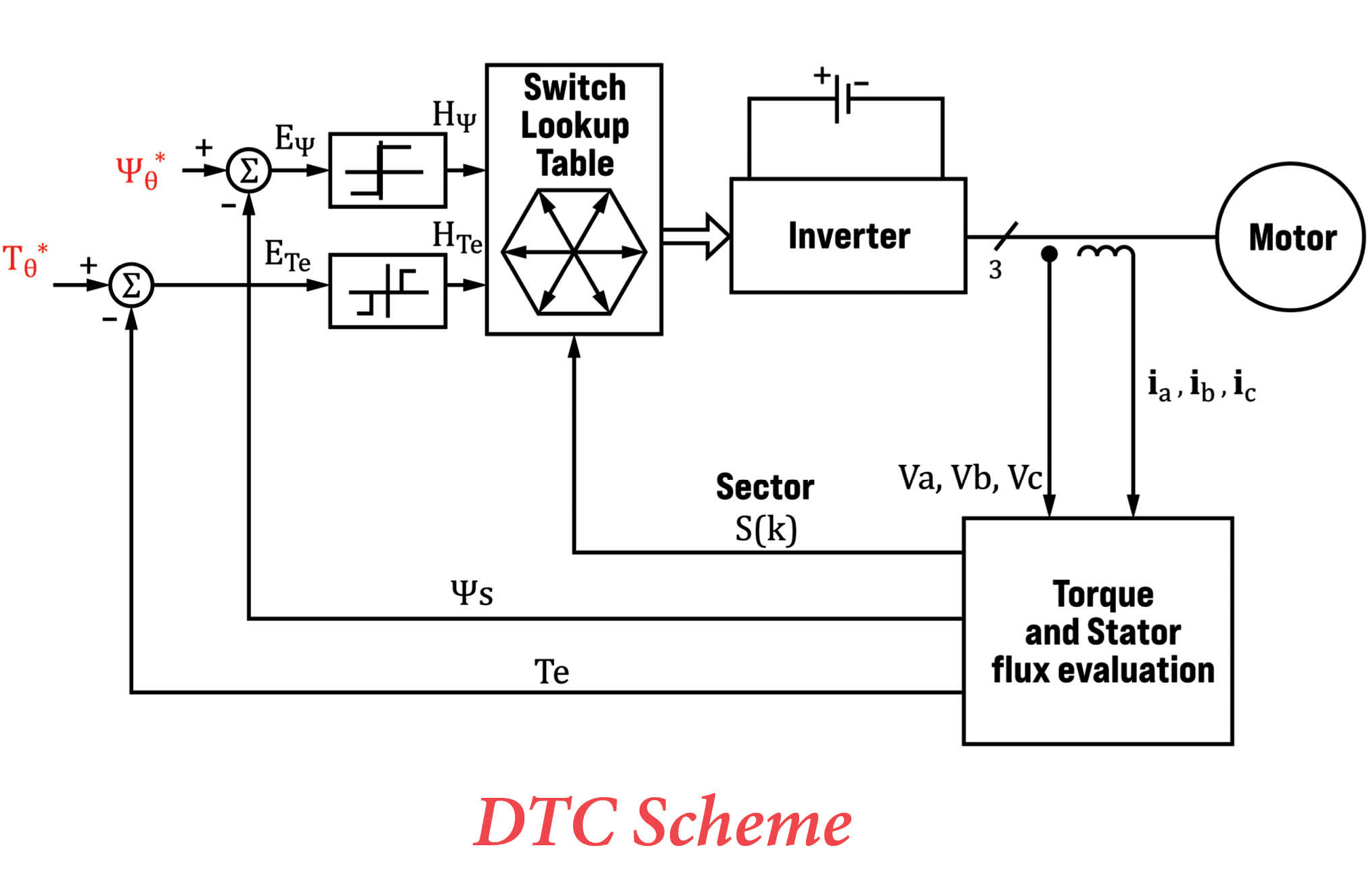
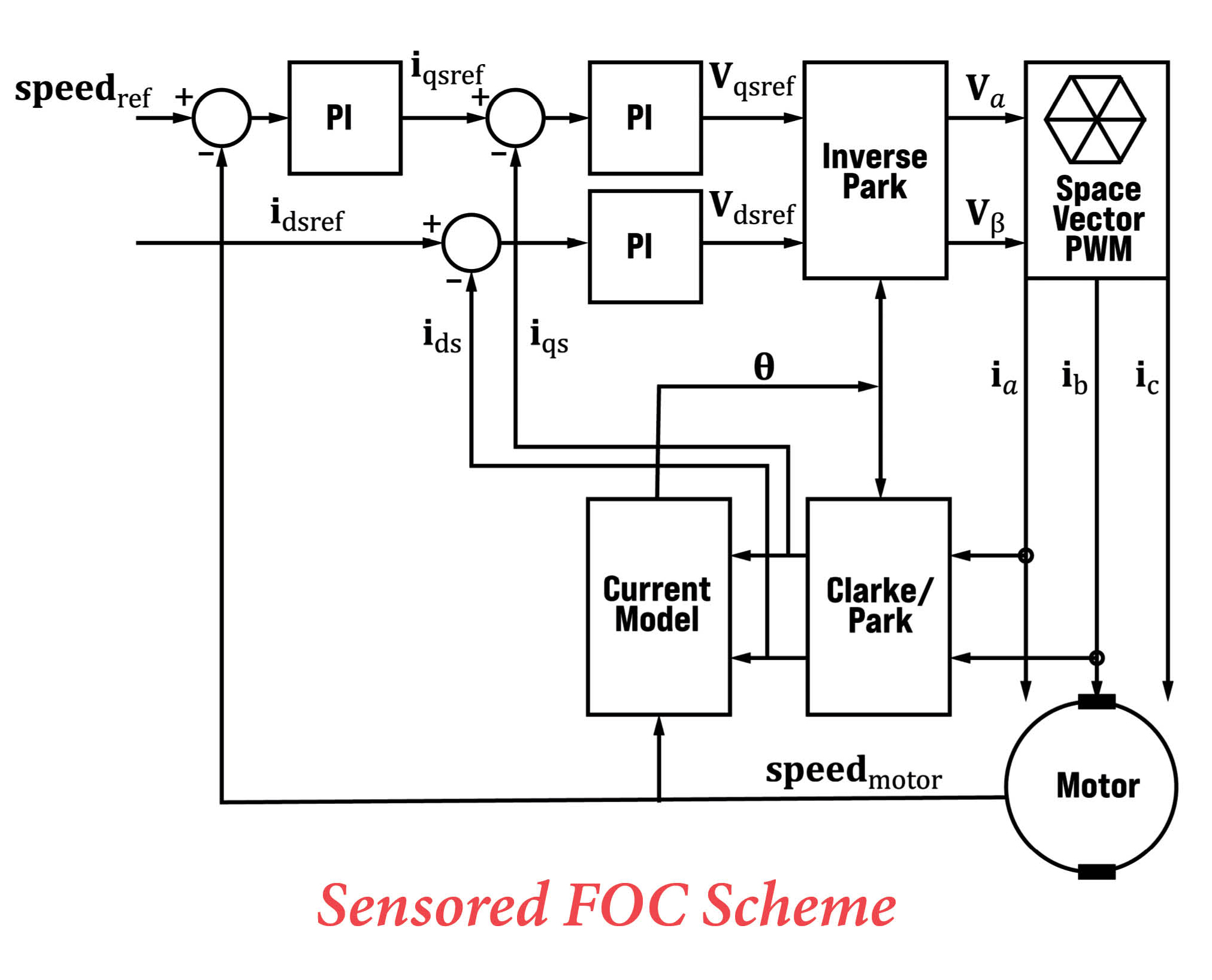
Finally, there are minor differences in efficiency due to the actual control strategy of the inverter. The vast majority of 3-phase inverters for traction applications will use what is generically called vector or field-oriented control, but there is another approach called direct torque control, which was originally developed because it was far less computationally-intensive. Back when the most powerful microcontrollers were 8 bits wide (and had to be programmed in assembly language, rather than more human-friendly languages like C or C++), the modest computing demands of DTC were very compelling, but just as Microsoft Windows has gotten ever more bloated as CPU speed and memory size have increased, so too have inverter design engineers been spoiled by the massive increase in computing power available in modern microcontrollers, DSPs (digital signal processors) and FPGAs (field-programmable gate arrays). In what almost seems like a redux of the Betamax vs VHS war of yesteryear, FOC is far more commonly used despite the fact that for best performance (read: getting the maximum torque per ampere and widest possible speed range) it requires a fearsome amount of calculations per second and an often-impractical level of knowledge of the motor parameters (because a lot of those parameters either have loose tolerances to begin with—like the permeability of electrical steel—or change with temperature—like the bulk resistivities of all metals).
Broadly speaking, FOC is better at maintaining a constant speed and delivering smooth torque, particularly at low RPM, while DTC has better dynamic response and much less need to predict the motor parameters to operate correctly.
There are a huge number of permutations of both DTC and FOC, but broadly speaking, FOC is better at maintaining a constant speed and delivering smooth (i.e. non-pulsating) torque, particularly at low RPM, while DTC has better dynamic response and much less need to know and/or predict the motor parameters to operate correctly, and therefore is much less sensitive to changes in such. As for differences in overall efficiency (i.e. motor plus inverter), the edge theoretically goes to FOC, if only because it has much less torque ripple, but in the real world it’s probably a toss-up, especially when paired with a PMSM. With an ACIM, however, classic FOC attempts to maintain full field flux at all times regardless of how much torque is being demanded to give the best transient response (from, for example, suddenly hammering on the accelerator pedal), whereas DTC with Space Vector Modulation (aka SVM, which most—if not all—modern implementations use) just picks the appropriate (or closest, anyway) voltage vector from a lookup table based on an internal motor model to deliver whatever field flux and torque is required for the load at that moment. One thing to be very skeptical of, though, are claims of delivering (or maintaining) good performance without rotor speed (ACIM) or position (PMSM) feedback, aka “sensorless” operation. Generally speaking, the maximum achievable torque per amp—and therefore the ultimate efficiency, really—is reduced when the inverter is deprived of rotor speed/position information, and this should be considered a limp-home mode, rather than a normal mode of operation.
Read more EV Tech Explained articles.
This article appeared in Issue 59: Jan-Mar 2022 – Subscribe now.