


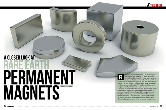
Rare earth magnets have gotten a lot of coverage in the EV press over the years for being expensive – especially back in 2011 when a supply disruption in China sent the prices up anywhere from fivefold for neodymium to 20-fold for dysprosium over the course of a few months – yet they are still a key component in the vast majority of traction motors found in EVs and hybrids (the notable exception is Tesla, which uses induction motors).
Magnets are manufactured industrially by running a current through a coil to apply an external magnetic field to a ferromagnetic material, but it is also possible to magnetize something by merely placing it in contact with another magnet, or even by striking it with a hammer. Ferromagnetic materials that are difficult to magnetize or demagnetize are called “hard,” and are preferred for use as permanent magnets – the subject of this article – while materials that are easy to magnetize or demagnetize are called “soft,” and are ideally used in transformers, inductors and electromagnets. Hard ferromagnetic materials feature molecules with a crystalline structure that is elongated in one direction – called anisotropy – and the process of magnetization is merely one of aligning all of the long axes in the same direction.
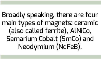
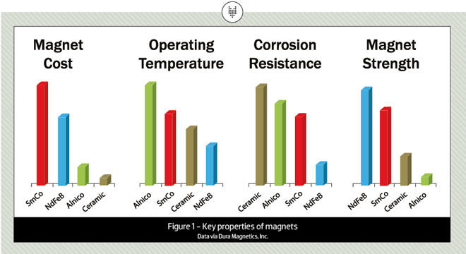
Broadly speaking, there are four main types of magnets: ceramic (also called ferrite), AlNiCo, Samarium Cobalt (SmCo) and Neodymium (NdFeB). The last type is the one most commonly used in traction motors for hybrids and EVs. Key properties of the four magnet types are summarized in Figure 1.
Cost and corrosion resistance are self-explanatory, although it should be emphasized that NdFeB magnets are exceptionally prone to corrosion and must be protected with some kind of coating or plating before exposure to the air. The significance of operating temperature is not quite as obvious as it might seem, however. All magnetic materials lose their magnetic properties at a certain temperature called the Curie point, and this is invariably fatal to permanent magnets. However, irreversible loss of magnetism can also occur at temperatures well below the Curie point, and it is this effect that really defines the operating temperature of a magnet. For example, the Curie point for NdFeB is 310-350° C, depending on the grade, but the maximum operating temperature ranges from 80° to 180° C. Conversely, AlNiCo magnets have the highest Curie point – in the range of 800-860° C – and can be used at up to 530° C.
Magnet strength is the most deceptive specification, because it is the product of remanence, which is the residual flux density (or B, usually measured in Gauss, or G), and coercive force (or H, usually measured in Oersteds, or Oe), which indicates how strong an external magnetic field is needed to fully demagnetize a magnet.
To put remanence into perspective, consider that the strongest grade of NdFeB magnet, N52, is rated for around 14,000 G, and a 1-inch-diameter x 2-inch-long magnet made of the stuff would require over 85 pounds of force to pull it from a steel block (or another magnet of similar or larger size).
Coercive force is a bit trickier to understand, but it relates not only to how much magnetic effort, so to speak, is required to demagnetize a magnet, but also to how much effort is required to magnetize it to its maximum possible remanence value.
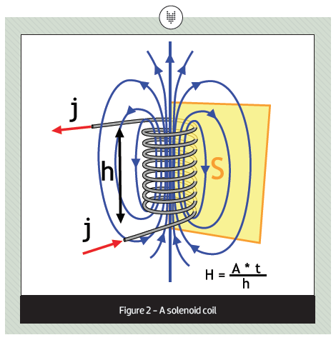
While you can make a magnet by simply placing a ferromagnetic material in contact with an existing magnet, the new magnet won’t be very strong, because to reach maximum remanence you need to apply sufficient coercive force to saturate the ferromagnetic material, and for anything but the weakest ceramic magnets, that generally requires using a multi-turn air-core solenoid coil through which a (usually) large current is passed to create an intense magnetic field. This produces a coercive force proportional to the amount of current times the number of turns divided by the height of the coil in meters. To convert from this electrically-generated coercive force to the Oersteds usually specified for magnets, divide by approximately 80 (the actual division ratio is 1,000/4Π). So a 1 Oe coercive force is approximately equal to 80 A*turns/m, which could be generated by any of the following combinations: 20 A*4 turns/1 m; 2 A*4 turns/10 cm; 8 A*1 turn/10 cm; etc.
Now consider that a high-grade NdFeB magnet has an intrinsic coercive force in the range of 11,000 Oe, and the staggering magnitude of what it takes to demagnetize one of these beasts should be apparent (~880,000 A*t/m!). Magnetizing that same ferromagnetic material in the first place, however, requires somewhere in the range of 2x to 4x the same coercive force. Fortunately, such an intense field only needs to be applied momentarily, so a practical approach is to charge up a capacitor bank, then dump that charge all at once into a coil made of copper tubing through which coolant flows. Peak currents for appropriately sized coils will still exceed 10 kA, however; after all, you can’t cram 100 turns of copper tubing into a 10 cm-tall coil…unless it’s capillary tubing.
In contrast, the strongest grade of AlNiCo magnet – 8HE – has a residual flux density in the range of 9,000 Gauss, which is comparable to some of the rare earth magnets, but a coercive force of 1,600 Oe, making it relatively easy to demagnetize. In fact, an AlNiCo magnet will demagnetize on its own if a magnetic shunt (also called a keeper) isn’t used to bridge its North and South poles together. The low coercive force is also the reason that AlNiCo drops to dead last in the rankings above, despite being a “stronger” magnet than the typical dark gray ceramic types.
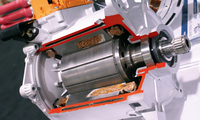
Resistance to demagnetization is especially important for magnets used in motors, as the mechanism by which motors work is the interaction of a fixed magnetic field – which in an AC motor is supplied, somewhat perversely, by the rotor – with a rotating magnetic field, which in an AC motor is created by sequentially energizing coils of wires arrayed about the circumference of the stator with an inverter. Using strong magnets that are easily demagnetized for the fixed field – such as AlNiCo – will result in a progressive loss of torque just from sitting around, even more loss from normal use, and a catastrophic loss of torque if subjected either to overcurrent or if there is a timing mismatch between the magnetic fields from the stator coils and the position of the rotor’s magnetic poles. Also, an intentional timing mismatch between rotor and stator is used to counteract some of the rotor’s field at high RPMs – this is called field weakening, logically enough – and is necessary to reduce the back EMF generated by the motor (if the back EMF exceeds the battery voltage, then the motor becomes a generator).
NdFeB magnets are the current champions in both maximum field strength and in resisting demagnetization, but their Achilles heel is a very low maximum operating temperature. The standard N grade will start to experience reversible/minor demagnetization at 60° C, and the recommended maximum operating temperature is 80° C; above that, irreversible loss of magnetism occurs. By adding the heavy rare earth metals dysprosium or terbium to the alloy, the maximum operating temperature can be increased to as high as 180° C, but with some reduction in maximum remanence, and both of those alloying elements are much more expensive – and have more volatile price swings – than neodymium. The average spot price in March 2017, as reported by the Shanghai Metals Exchange, was $51/kg for neodymium and $242/kg for dysprosium.
Still, a 180° C maximum operating temperature matches the standard grades of magnet wire insulation, so this is generally considered “good enough” (it should be noted that the resistance of copper increases by 0.4%/° C, so increasing the maximum operating temperature isn’t necessarily desirable in the first place). Also, about 90% of the losses in the IPM motor come from the stator, but since the stator is very close to the rotor – separated by an air gap of a couple of millimeters or less – some heat transfer is inevitable.
So what about ditching the magnets completely, as in an induction motor? Unsurprisingly, there are compelling arguments for both technologies – a more comprehensive look at these (including the efforts to reduce or eliminate the use of rare earth magnets) could be the subject of a future article. Broadly speaking, however, an induction motor will be larger and less efficient for a given power output than an IPM motor. It will also have a lower power factor – which basically means some of the current rating of the inverter can’t be used to produce useful torque. On the other hand, the induction motor is practically indestructible, it doesn’t require precise rotor position feedback to deliver its maximum possible torque and there is no possibility of the failure mode called “uncontrolled generation,” which results when the inverter misfires or shuts down while field weakening is in effect – the IPM motor instantly turns into a generator, and can force such a huge current to backfeed through the inverter that it destroys the latter, and perhaps itself.
Read more EV Tech Explained articles.
This article originally appeared in Charged Issue 32 – July/August 2017 – Subscribe now.