


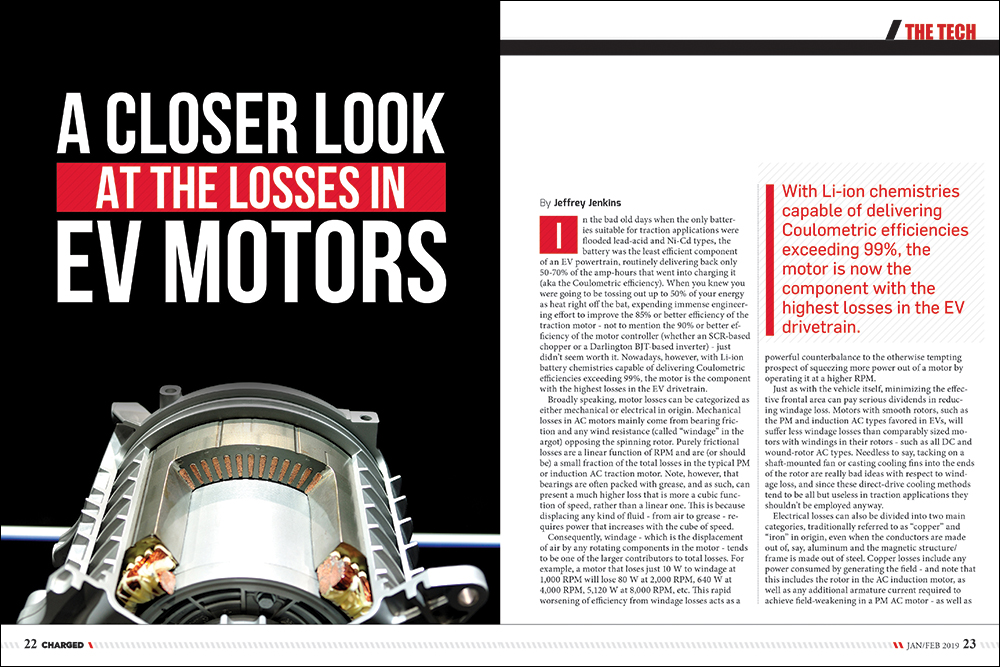
In the bad old days when the only batteries suitable for traction applications were flooded lead-acid and Ni-Cd types, the battery was the least efficient component of an EV powertrain, routinely delivering back only 50-70% of the amp-hours that went into charging it (aka the Coulometric efficiency). When you knew you were going to be tossing out up to 50% of your energy as heat right off the bat, expending immense engineering effort to improve the 85% or better efficiency of the traction motor – not to mention the 90% or better efficiency of the motor controller (whether an SCR-based chopper or a Darlington BJT-based inverter) – just didn’t seem worth it. Nowadays, however, with Li-ion battery chemistries capable of delivering Coulometric efficiencies exceeding 99%, the motor is the component with the highest losses in the EV drivetrain.
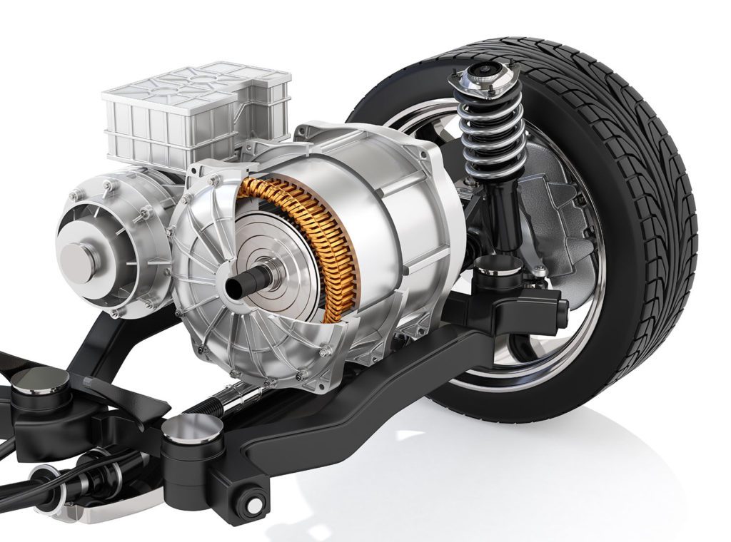
With Li-ion battery chemistries capable of delivering Coulometric efficiencies exceeding 99%, the motor is the component with the highest losses in the EV drivetrain.
Broadly speaking, motor losses can be categorized as either mechanical or electrical in origin. Mechanical losses in AC motors mainly come from bearing friction and any wind resistance (called “windage” in the argot) opposing the spinning rotor. Purely frictional losses are a linear function of RPM and are (or should be) a small fraction of the total losses in the typical PM or induction AC traction motor. Note, however, that bearings are often packed with grease, and as such, can present a much higher loss that is more a cubic function of speed, rather than a linear one. This is because displacing any kind of fluid – from air to grease – requires power that increases with the cube of speed.
Consequently, windage – which is the displacement of air by any rotating components in the motor – tends to be one of the larger contributors to total losses. For example, a motor that loses just 10 W to windage at 1,000 RPM will lose 80 W at 2,000 RPM, 640 W at 4,000 RPM, 5,120 W at 8,000 RPM, etc. This rapid worsening of efficiency from windage losses acts as a powerful counterbalance to the otherwise tempting prospect of squeezing more power out of a motor by operating it at a higher RPM.
Just as with the vehicle itself, minimizing the effective frontal area can pay serious dividends in reducing windage loss. Motors with smooth rotors, such as the PM and induction AC types favored in EVs, will suffer less windage losses than comparably sized motors with windings in their rotors – such as all DC and wound-rotor AC types. Needless to say, tacking on a shaft-mounted fan or casting cooling fins into the ends of the rotor are really bad ideas with respect to windage loss, and since these direct-drive cooling methods tend to be all but useless in traction applications they shouldn’t be employed anyway.
Electrical losses can also be divided into two main categories, traditionally referred to as “copper” and “iron” in origin.
Electrical losses can also be divided into two main categories, traditionally referred to as “copper” and “iron” in origin, even when the conductors are made out of, say, aluminum and the magnetic structure/frame is made out of steel. Copper losses include any power consumed by generating the field – and note that this includes the rotor in the AC induction motor, as well as any additional armature current required to achieve field-weakening in a PM AC motor – as well as the more obvious resistive loss, and the less obvious AC losses (from skin and proximity effects).
Resistive loss, also referred to as I2R loss, tends to dominate in traction motors because they are so frequently operated at high currents and low RPMs. In this situation, total motor power is quite low – being the product of RPM and torque – but I2R doesn’t care about the RPM (voltage) component, hence when starting a load from a dead stop the efficiency of a traction motor will be downright abysmal. Using a series DC motor as an example just to keep things simple, say it takes 500 A to begin accelerating a vehicle from a dead stop and the total resistance of the windings, brushes, etc, is a rather minuscule-seeming 40 mΩ. This results in an I2R loss of 10 kW, which doesn’t seem so minuscule after all, and since the shaft is barely turning – because the vehicle is barely moving – the efficiency will be just a hair over 0%. A similarly egregious amount of loss is incurred in the rotor of an AC induction motor as the shorting bars in the rotor basically act as a single turn secondary while the phase windings constitute the primary of a 3-phase transformer. It is not unusual for 10 kA or more to flow in the shorting bars under near-stalled conditions, particularly with those methods of Field-Oriented Control that attempt to operate the rotor at full field flux all the time. Still, as dramatic as this all might seem, supplying the field in non-PM field motors usually consumes about 1% of the electrical input power.
Purely resistive loss is incurred at frequencies from DC to light, so to speak, while skin and proximity effect can be thought of as resistive losses that increase with frequency. Skin effect is the tendency for current to become increasingly constrained to the outer perimeter of a conductor as frequency goes up. It is caused by tiny loops of currents being induced in a wire – eddies – by the very alternating current which is flowing through it. Such loops of eddy current are proportional to the magnitude of the source current, of course, but also the rate of change of the magnetic field (that is, the frequency of the source current). These eddy currents oppose the flow of current in the center of the conductor and add to it on the periphery, which is why the current becomes increasingly constrained to the periphery. For a more concrete example, a copper conductor with a diameter of 11.7 mm (AWG #0000) can carry 500 A at a temperature rise of 30° C, but skin effect will start reducing its effective diameter (and ampacity) at a mere 125 Hz, or a synchronous speed of 7,500 RPM in a 2-pole AC motor!
The usual solution to skin effect is to divide a single large wire into many smaller ones that are insulated from each other but paralleled, however this can lead to more losses from proximity effect, which is basically the same as skin effect except it is caused by the AC current from other nearby conductors inducing the eddy currents. Basically, the more layers to a winding the higher the proximity effect losses. Transformer designers – particularly at very high power levels and/or high frequencies – have to go to extreme lengths to minimize proximity effect, but traction motors tend not to suffer as much from either skin or proximity effect, as they don’t normally operate at high speed and high torque at the same time (or not for very long, anyway, before the driver is pulled over for speeding).
As briefly touched upon under skin effect, eddy currents arise because any time-varying magnetic field induces a current in any nearby conductors, including the source conductor. It is more correct to say that a time-varying magnetic field induces a voltage in nearby conductors (including itself) and that voltage causes a current to flow in a loop about the source conductor. The induced voltage is fixed for a given separation distance, area of the loop and rate of change of magnetic flux, so the current which results will be inversely proportional to the loop resistance and directly proportional to loop area and source current frequency. Consequently, eddy currents are higher in better conductors like silver and copper than they are in poorer conductors like electrical steel or ferrite (which is nearly an insulator). In fact, “electrical steel” is so-called because it is an alloy of iron and silicon specifically designed to maximize bulk resistivity without unduly compromising its magnetic qualities such as hysteresis loss and saturation flux density.
The absolute bulk resistivity of electrical steel is still rather low, however, and while that of ferrite is very high, it also has a much lower saturation limit (0.35 Tesla, typically, vs 1.3-1.5 Tesla), so isn’t really feasible to use in the armature of motors (unless they are operated at a synchronous frequency above, say, 10 kHz, which works out to 600 kRPM [!] for a 2-pole motor). Fortunately, reducing the loop area is entirely possible by simply breaking up one monolithic structure into a stack of laminations which are insulated from each other (usually with a thin lacquer or oxide coating). The thinner the laminations used, the lower the loss from eddy currents, but note that as the laminations get thinner their insulating coating becomes a larger proportion of the total thickness, so there is a practical limit to how thin a lamination can be used. In more concrete terms, the typical lamination thickness is around 0.5 mm for transformers or motors operating at 60 Hz (or 3,600 RPM synchronous speed for a 2-pole AC motor).
Another major contributor to iron losses is from hysteresis, which is basically the resistance to a change in the direction of magnetization or flux density.
The last major contributor to iron losses is from hysteresis, which is basically the resistance to a change in the direction of magnetization or flux density. Since the armature in all motors is excited with AC current – whether supplied by an external inverter or brushes and commutator – its magnetic circuit repeatedly experiences large swings in flux density between opposing polarities. Magnetic materials that tolerate this sort of operation need to be “soft,” – that is, easy to magnetize (low coercivity) while not retaining that magnetic moment (low remanence). Conversely, materials that are difficult to magnetize (and demagnetize) are classified as “hard,” and they tend to make good permanent magnets. Hysteresis loss is basically a measure of how soft a magnetic material is, then, and it is most strongly dependent on flux density (typically proportional to the 1.6 power).
“Stray” losses are those that either don’t seem to neatly fit into any one category or which are more like rounding errors rather than significant factors.
Finally there are various “stray” losses, which are those that either don’t seem to neatly fit into any one category or which are more like rounding errors rather than significant factors. The most notable example of such is magnetic leakage, which is basically any flux that doesn’t link the rotor and stator together (which means it doesn’t do any useful work). Worse still is that this unlinked flux also subtracts from the effective AC voltage exciting the armature (because it translates electrically into inductance). The last loss mechanism considered here is common-mode, capacitively-coupled current. This current results from the drive rapidly switching its phase outputs between 0 V and bus voltage (typically around 350 V) which then causes current to flow across any parasitic capacitances along the way. While the actual power loss from these currents tends to be minimal, they can still erode bearings (through what is effectively “electrical discharge machining”) and damage the insulation on the phase windings. Oh, and cause the vehicle to fail its EMI/RFI emissions test. The quick and dirty solution is to slow down the switching speed of the bridge switches in the inverter, but that increases their losses. Yet another Catch-22, then…Welcome to the wonderful world of engineering!
Read more EV Tech Explained articles.
This article appeared in Charged Issue 41 – January/February 2019 – Subscribe now.