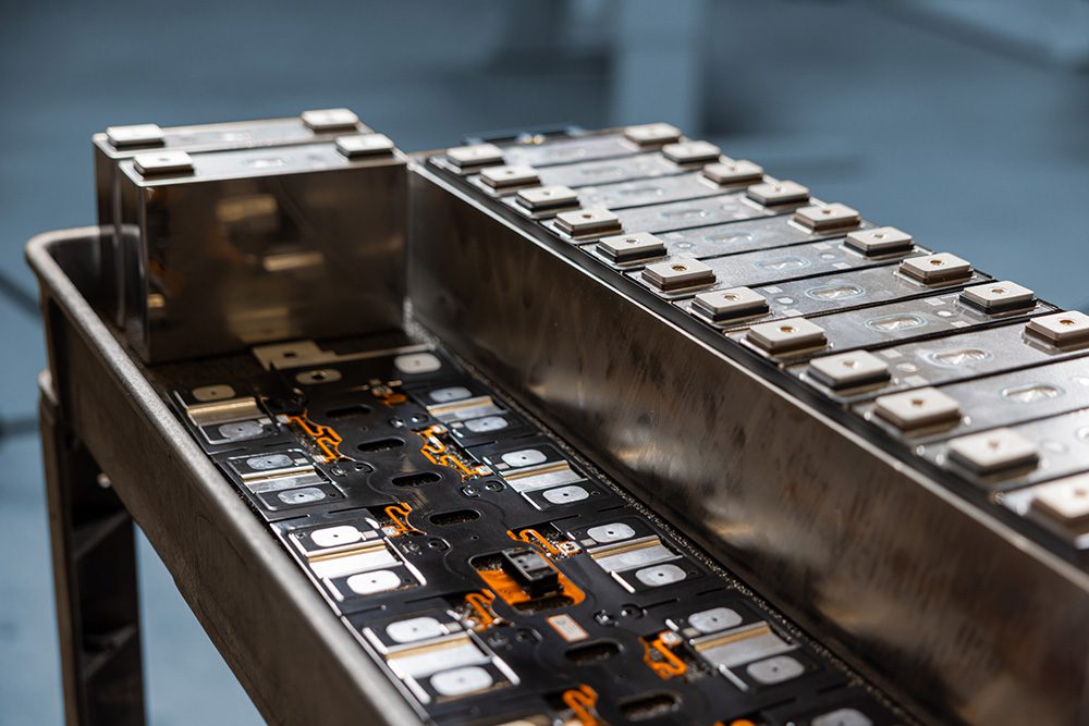
Pretty much every electronic circuit that handles significant power utilizes some means of measuring current, whether to simply protect against overload or because it is a basic functional requirement. In this article we’ll cover some of the more common devices and circuit techniques for measuring current in the major subsystems of an EV, including when to choose one over the others.
Current can be sensed or measured in one of two ways, really: via the voltage drop across a resistor of some sort, otherwise known as a shunt, or via the intensity of the magnetic field which radiates from any current-carrying conductor. In the former case, the shunt can be an actual resistor made expressly for the purpose, or it could be a creative use of circuit/component parasitics, such as the on-resistance of a MOSFET, the winding resistance of an inductor, or even a trace on a printed-circuit board. Despite the differences in form, all shunts perform the same function, which is to drop a predictable amount of voltage vs current, but don’t let that apparent simplicity fool you into thinking shunts are foolproof.
There is an even more diverse array of current sensors which output a signal in proportion to a magnetic field, from the mundane current transformer to the truly exotic fiber-optic interferometer (sadly, not used in any EVs I’m aware of, but see ABB’s catalog if you need to measure 600 kA). Which type of current sensor to choose depends on several factors, such as whether DC must be measured, AC frequency range, current range, overload capability (or tolerance, at least), linearity, accuracy and, of course, budget. Note that all magnetic-type current sensors automatically isolate the circuit being monitored from the circuit doing the monitoring, and this benefit alone is often the deciding factor in choosing one of them over a shunt.
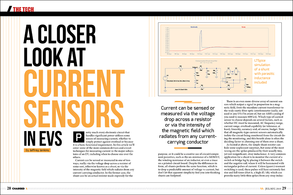
As hinted at above, the simple shunt resistor can hide some unpleasant surprises, but some of the most vexing are the spikes produced by their usually tiny, yet not insignificant, stray inductance. A very common application for a shunt is to monitor the current of a switch or bridge leg by placing it between the switch and the negative rail, where it will be hammered with rectangular pulses of current. Unless (quasi-) resonant switching is used, these pulses will have extremely fast rise and fall times (that is, a high dI / dt), which can provoke nasty little thin spikes from any stray inductance in the way. For a concrete, yet realistic, example, if a shunt has a mere 1 nH of stray inductance, then it will generate a short spike at every transition of 1 V if 20 A is switched in 20 ns (V = L * [dI / dt]). Given that many PWM controller ICs have an overcurrent trip at 1 V, it’s clear that spikes like this can cause all sorts of trouble. The usual solutions are to integrate the spikes away with an RC filter that has the same time constant as that of the shunt (that is, R * C = L / R), or else ignore, or blank out, the leading edge of the current sense signal (or both). An RC integrator slows down the transient response of the shunt, however, while leading-edge blanking disables overcurrent protection for the time it is in effect (and also enforces a minimum switch on time in current mode control). Increasing the resistance of the shunt while somehow maintaining the same inductance will help, but at the expense of generating more heat (and therefore lower efficiency) from increased I2R losses.
Two other potential issues with shunts are interrelated: the signal they produce is obviously not isolated, which means that they are not intrinsically safe; and also, they are exposed to any “common mode” voltage, which can produce huge errors in the signal conditioning circuit. Common mode voltage is basically that which is the same at two different nodes in a circuit, as referred to circuit ground. A classic example of where this is a problem is in the case of monitoring the phase current from an inverter. In this position the current sensor is in between the inverter supplying a chopped voltage and the motor load it drives, so neither end is grounded, and since a shunt will have a negligibly low resistance, practically the same magnitude of chopped voltage will be present at both ends of it; that is, in common mode. Reading a 100 mV to 1 V signal from the shunt in the presence of what is effectively the traction battery voltage requires a differential amplifier to (theoretically) ignore the common mode voltage and only amplify the difference voltage, but in the real world this doesn’t happen because of imperfect common mode rejection ratio (usually given in dB). The simplest one op-amp, unity-gain differential amplifier circuit can only suppress common mode voltage by 66 dB if 0.1% resistors are used, which means 300 V in common mode will result in 150 mV of error at the output! Of course, there are other differential amplifier circuits with higher intrinsic CMRR (e.g. the instrumentation amplifier) but they cost more money (and board area) and still don’t isolate the signal, so the “cheap and cheerful” shunt might not be either of those things!
It’s not all bad news for shunts, however. They tend to be very robust and can usually withstand enormous overloads (the signal conditioning circuit might “hit the stops” – that is, run out of supply voltage, however). Also, if a zero temperature coefficient metal is used (e.g. Manganin), then stability over time and temperature will be unparalleled. Finally, shunts have an almost unlimited dynamic range – limited only by the signal-conditioning circuit, really. When you need to accurately measure over a span of several decades (for example, to keep track of traction battery state of charge) then only a shunt will do.
Conversely, if you can tolerate poorer absolute accuracy and/or drift over time/temperature, but really need isolation, then a magnetic current sensor will likely prove superior. The first of these we’ll cover is the Hall effect type, which relies on an effect discovered by Edwin Hall all the way back in 1879. Basically, whenever an external magnetic field is applied perpendicular to the flow of current in a conductor, it will bend the path the current takes, and this sets up a slight charge imbalance across the width of the conductor. The Hall effect occurs in all conductors, but the voltage produced is downright minuscule, even in special semiconductors made for the job: we’re talking a few microvolts to millivolts of voltage difference per milliTesla of magnetic field intensity, so follow-on amplification is de rigueur.
The output of the Hall sensor can be amplified directly for use by external circuits – which is called open-loop operation – and while the accuracy and linearity of this approach is poor, it is capable of a higher bandwidth for a given peak current. Alternatively, the Hall sensor can be used to drive a counteracting current through a coil wound on the same core to cancel out the field from the monitored conductor, and the output made proportional to the control current, which is called closed-loop operation. The advantage of the latter approach is that any non-linearity caused by the core material is nulled out. Also, because the net field in the core is close to zero, a closed-loop sensor can generally handle a higher current for a given core area (at least until the nulling circuit runs out of headroom). Still, accuracy and linearity aren’t on par with a good shunt-based design: one popular manufacturer quotes an accuracy of 1%, a temperature coefficient of +/- 0.1% / K, and initial and hysteresis offsets (which effectively set the minimum resolvable current) of +/- 20 mV out of a full scale value of +/- 4 V. Consequently, a 500 A full scale model will be unable to resolve differences of less than 2.5 A accurately. Another downside is the result of the magnetic core, which puts a hard upper limit on the overload rating because once the nulling circuit runs out of current to counteract the field from the conductor the core will quickly saturate. The aforementioned 500 A full scale model has an overload rating of 900 A, which might seem impressive until you consider that most shunts can easily tolerate brief overloads of 10x or more (though, again, whether a useful signal is still obtainable depends on the signal conditioning circuit).
A similar type of sensor – especially in physical form factor and typical output scaling – uses the Giant MagnetoResistance effect, or GMR, in which the bulk resistance of alternating layers of magnetic and non-magnetic materials changes in proportion to magnetic field intensity. The main advantage of GMR over Hall effect is higher sensitivity – so it is capable of measuring lower currents accurately – but one major downside for OEMs is that relatively few manufacturers offer current sensors based on GMR at this time (it first found wide application in hard disk drive read heads).
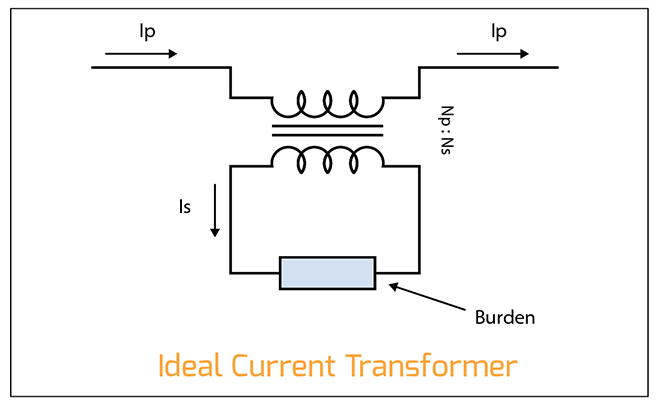
The last commonly used type of current sensor is the current transformer, which comes in two very different flavors: conventional and Rogowski. The conventional current transformer usually consists of a single-turn primary and a 10- to 1,000-turn secondary wound on a magnetic core material appropriate for the frequency range. Since transformers conserve amp * turns, the current in the secondary will be reduced by the turns ratio, and only a load, or burden, resistor is then needed to scale the output voltage. For example, to generate a 1 V signal at 10 A with a shunt requires a resistance of 0.1 Ω which will have a peak loss of 10 W (I2R again), but with a 1:100 current transformer the secondary current will be 100 mA, requiring a 10 Ω burden resistor to develop the same 1 V while reducing the loss to 100 mW. Current transformers are also highly linear and can achieve nearly as wide a dynamic range as shunts, with isolation thrown in for free. The main downside is the practical lower limit on frequency (core area required is inversely proportional to frequency), so these can’t really be used for current feedback on a traction inverter’s outputs (which deliver a very low AC frequency at low RPM).
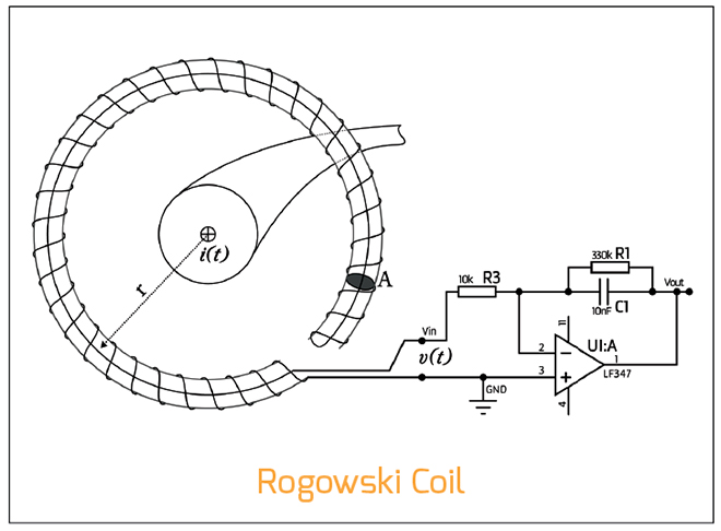
The other type of current transformer is the Rogowski coil, which is simply an air-core solenoid bent into a nearly-closed circle around the conductor to be monitored. The lack of a magnetic core implies an ability to read very high frequency and amplitude currents, because air doesn’t suffer from non-linearity or saturation, unlike all ferromagnetic materials. However, the output of a Rogowski coil is proportional to the rate of change in current (i.e. dI / dt), rather than just the magnitude of current itself, so its output has to be integrated, first, and the integrator inevitably limits the frequency and amplitude range that can be covered. Rogowski coils are rarely used as current sensors in equipment below 1 kA or so, but they do find widespread use as current probes for meters and oscilloscopes. The very simplicity of their design – and consequent cheapness to manufacture – strongly suggests they will be used more in the future, especially in OEM EVs that are already produced in the kind of volumes that most power supply and motor drive manufacturers could only dream about.
Read more EV Tech Explained articles.
This article appeared in Charged Issue 44 – July/August 2019 – Subscribe now.