


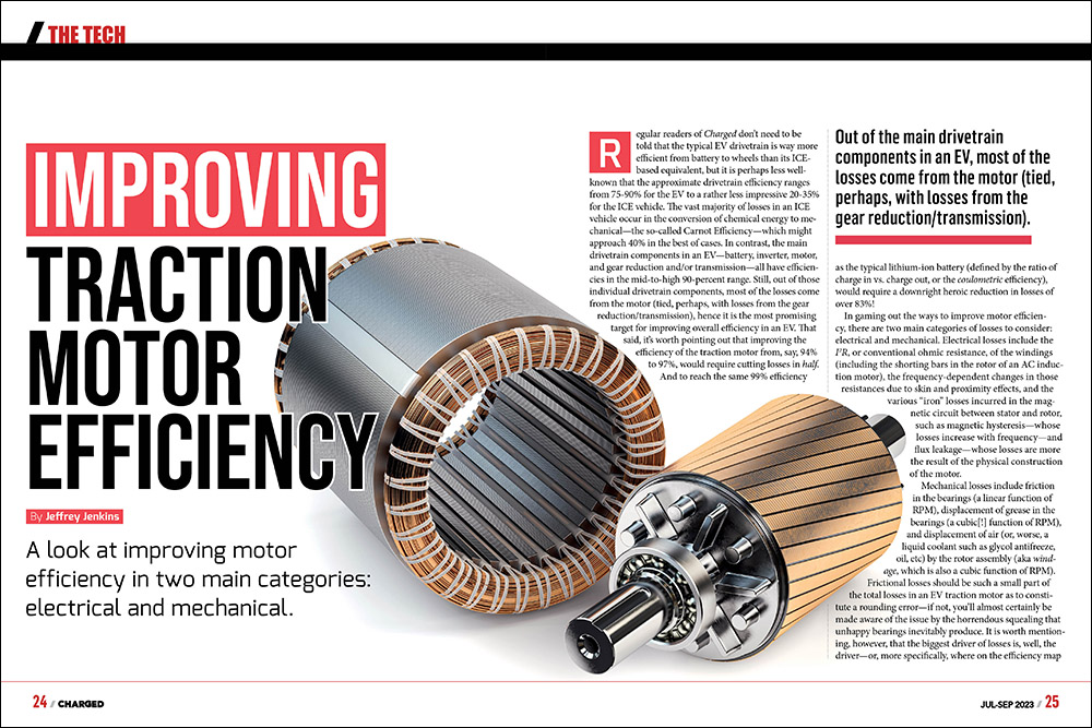
A look at improving motor efficiency in two main categories: electrical and mechanical.
Regular readers of Charged don’t need to be told that the typical EV drivetrain is way more efficient from battery to wheels than its ICE-based equivalent, but it is perhaps less well-known that the approximate drivetrain efficiency ranges from 75-90% for the EV to a rather less impressive 20-35% for the ICE vehicle. The vast majority of losses in an ICE vehicle occur in the conversion of chemical energy to mechanical—the so-called Carnot Efficiency—which might approach 40% in the best of cases. In contrast, the main drivetrain components in an EV—battery, inverter, motor, and gear reduction and/or transmission—all have efficiencies in the mid-to-high 90-percent range. Still, out of those individual drivetrain components, most of the losses come from the motor (tied, perhaps, with losses from the gear reduction/transmission), hence it is the most promising target for improving overall efficiency in an EV. That said, it’s worth pointing out that improving the efficiency of the traction motor from, say, 94% to 97%, would require cutting losses in half. And to reach the same 99% efficiency as the typical lithium-ion battery (defined by the ratio of charge in vs. charge out, or the coulometric efficiency), would require a downright heroic reduction in losses of over 83%!
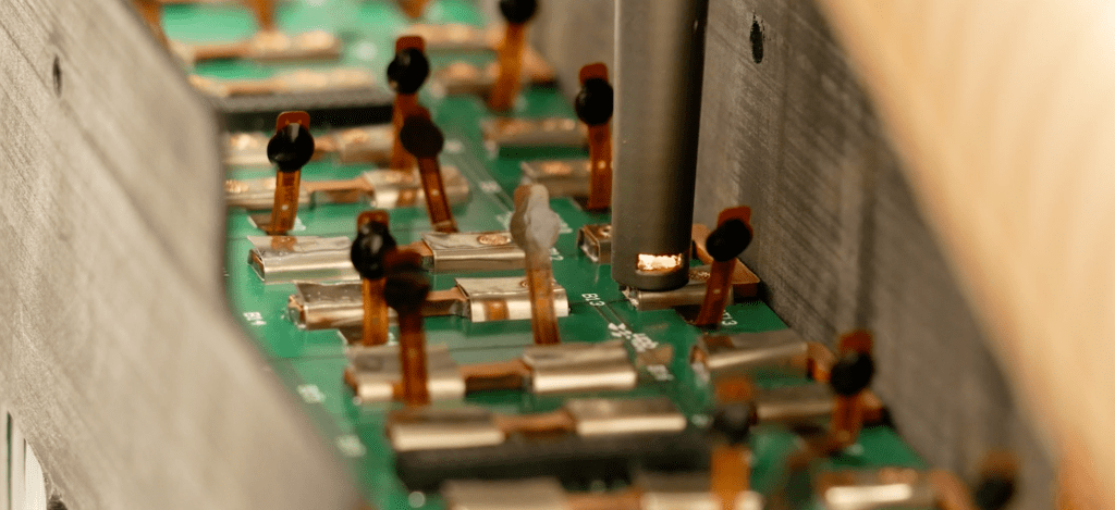
Out of the main drivetrain components in an EV, most of the losses come from the motor (tied, perhaps, with losses from the gear reduction/transmission).
In gaming out the ways to improve motor efficiency, there are two main categories of losses to consider: electrical and mechanical. Electrical losses include the I2R, or conventional ohmic resistance, of the windings (including the shorting bars in the rotor of an AC induction motor), the frequency-dependent changes in those resistances due to skin and proximity effects, and the various “iron” losses incurred in the magnetic circuit between stator and rotor, such as magnetic hysteresis—whose losses increase with frequency—and flux leakage—whose losses are more the result of the physical construction of the motor.
Mechanical losses include friction in the bearings (a linear function of RPM), displacement of grease in the bearings (a cubic[!] function of RPM), and displacement of air (or, worse, a liquid coolant such as glycol antifreeze, oil, etc) by the rotor assembly (aka windage, which is also a cubic function of RPM). Frictional losses should be such a small part of the total losses in an EV traction motor as to constitute a rounding error—if not, you’ll almost certainly be made aware of the issue by the horrendous squealing that unhappy bearings inevitably produce. It is worth mentioning, however, that the biggest driver of losses is, well, the driver—or, more specifically, where on the efficiency map the motor spends most of its time operating (see Fig. 1).
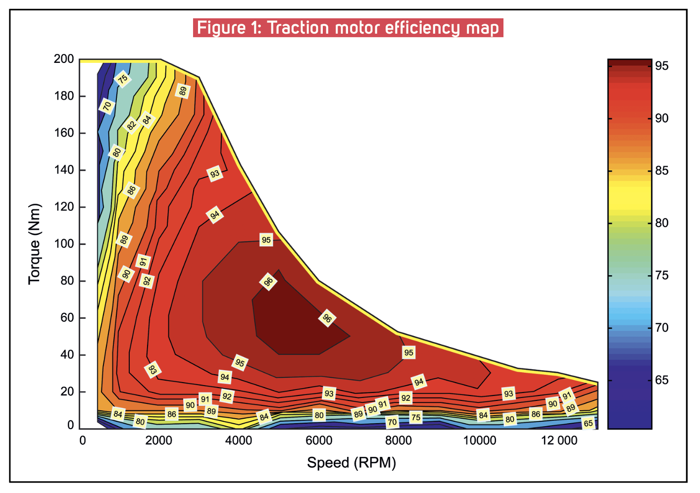
While the specific efficiency values will vary from motor to motor, and with application, of course, the general distribution of those values will tend to apply to all cases, and the key takeaway here is that operating at the extremes of the torque or speed capability of any given motor results in drastically lower efficiency (plummeting to zero, in fact, at max torque and zero RPM—that is, stalled—or any RPM and zero torque—that is, unloaded).
The key takeaway here is that operating at the extremes of the torque or speed capability of any given motor results in drastically lower efficiency.
Minimizing electrical losses requires a multi-pronged approach, and that usually implies that there will be some tradeoffs involved. For example, torque is proportional to magnetic flux intensity, which itself is proportional to the product of current and the number of turns in each armature winding, so doubling the number of turns cuts the required current to produce the same torque in half. This will result in a winding with twice the resistance, but since losses are proportional to current squared, the net effect is a 50% reduction in losses. So why not go with 10 times the turns and 1/10th the current—or however much further you want to take this argument? Well, the back EMF produced by a motor is proportional to the number of turns, too, so the battery voltage necessary to operate at a useful RPM would rapidly exceed what is practical.
Another approach is to use silver wire rather than copper (or aluminum) for the windings, netting a reduction in resistance of about 7% (or 39% for aluminum), albeit at a tough-to-swallow 100x increase in cost. However, when extrapolated to a theoretical useful working life of, say, 10,000 hours, at an average power of 20 kW and a cost per kWh of $0.20, that would save around $2,800 in electricity, making a fairly compelling argument for silver windings right there. Of course, the best winding material would be one with no resistance at all—that is, a superconductor—but the recently broken promise of LK-99 shows us that that goal is still some ways off in the future, and even if it were available today, there are other practical considerations, such as whether the superconducting material can be formed into a wire with an enamel insulating coating, as is needed for the windings in motors (and transformers, inductors and other electromagnetic components).
Resistive losses aren’t just a problem at high torque (i.e. high current) levels—they can sap efficiency at high RPM too, as the effective resistance of a wire rapidly increases above a certain frequency due, primarily, to the phenomenon colloquially known as “skin effect.” What basically happens is that an alternating current induces small loops, or “eddies,” of current in its own conductor. These eddy currents oppose the flow in the center of the wire and add to it in the periphery, hence it appears that the current is constrained to the outermost portion, or skin, of the wire. The effective depth that current will use in a conductor is inversely proportional to frequency, and since motor RPM is directly proportional to frequency, this sets an upper limit either on wire diameter (and therefore current) or RPM. The usual solution to minimizing skin effect is to break up a single wire into many individually insulated smaller wires—something which might need to be done, anyway, just to make winding the motor (or transformer, etc) practical. Note, however, that this increases the percentage of the winding area that is taken up by insulation, rather than copper (or silver, etc), so there is definitely a law of diminishing returns here.
Turning now to the iron losses in a motor, a commonly used rule of thumb for any electromagnetic device which handles alternating current is that the iron and copper losses should be approximately equal. As this rule of thumb implies, there are mutually exclusive tradeoffs between the two—for example, increasing the cross-sectional area to reduce flux density reduces iron losses but requires longer windings, which increases resistance (it also makes the motor significantly heavier). The vast majority of motors today use steel that is alloyed with silicon to construct the magnetic circuit—that is, the parts of the motor that conduct loops of magnetic field—as it combines a relatively high saturation flux density, good formability, high electrical resistance, and relatively low cost, but at the expense of less-than-impressive hysteresis losses (roughly equivalent to frequency-dependent losses in wires). Worse still is that the losses in a magnetic material tend to increase at an exponential rate with frequency and flux swing (typically to the 1.5-2.5 power, depending on material), meaning that a relatively small increase in inverter fundamental frequency (which determines RPM) or phase current (which determines torque) can result in an outsized increase in losses.
There are numerous magnetic materials with much lower losses, but few of them are suitable for use in motors. For example, the various ferrites commonly used in high-frequency magnetic components have a lower saturation flux density (in the range of 0.3-0.35 Tesla, compared to 1.8-2.0 Tesla for silicon steel) and are extremely brittle, so they’re difficult to form, and aren’t the best choice for a motor that will be bouncing along the road. Much more promising materials employ slight variations in the processing and/or alloying elements of silicon steel, resulting in either an extremely fine grain structure (nanocrystalline) or no grain structure at all (amorphous). Amorphous metals have been employed in transformers and motors for decades (and for those of a certain age, also in the heads in tape decks) and while they can achieve an impressive up to 70% reduction in losses (from around 1.4 W/kg to 0.4 W/kg, depending on frequency, flux swing, etc), they are more expensive to manufacture and more brittle (though not nearly as brittle as ferrite). Between the two variants, the nanocrystalline version has the edge in saturation flux density and mechanical properties, while amorphous is less expensive to produce and a more established material. Either way, reducing iron losses by up to 70% gets you closer to improving overall motor efficiency to that mythical 99% figure than the relatively meager contribution from silver wire, and possibly at a lower cost.
Reducing iron losses by up to 70% gets you closer to improving overall motor efficiency to that mythical 99% figure than the relatively meager contribution from silver wire, and possibly at a lower cost.
As mentioned earlier, frictional losses in the shaft bearings should be a tiny fraction of overall losses, so this isn’t really an area where further optimization is possible, although we should note that one insidious failure mode of motors supplied by a variable-frequency drive is spark erosion of the internal bearing surfaces caused by capacitively-coupled currents produced by the rapidly switching voltages from the inverter (i.e. from high dV/dt), hence the growing use of ceramics for the bearing balls and races. Otherwise, moving away from total-immersion liquid cooling—especially if the coolant is oil, which has a much higher viscosity than aqueous coolants like glycol and water—can significantly reduce windage loss. Another key factor is not operating at extremely high RPMs, as, again, windage loss scales with the cube of RPM, so a modest loss of 100 W at, say, 3,000 RPM turns into a far-less-tolerable 2.7 kW of loss at 9,000 RPM.
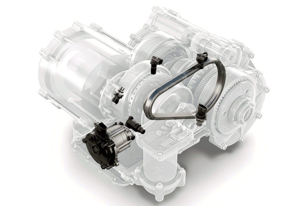
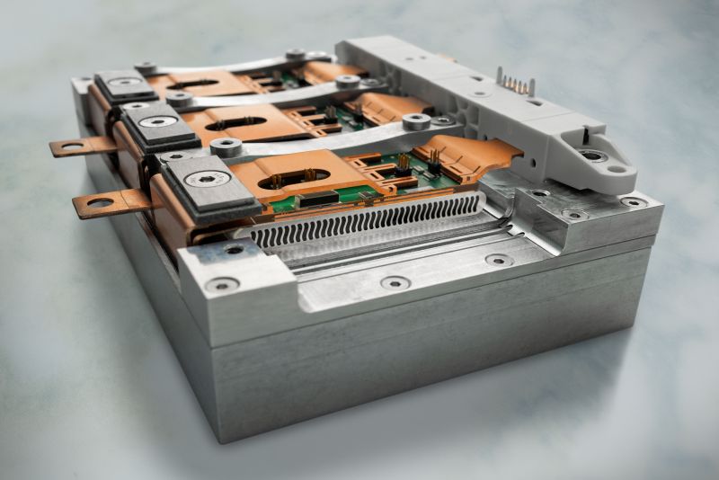
The CVT4EV is a continuously variable transmission with a pushbelt that Bosch says can increase the efficiency of light commercial EVs by more than 4 percent.
Picture: Bosch
On a related note, the use of multi-speed transmissions (either mechanical or the rather novel electronic approach discussed below) rather than the single-speed gear reduction most commonly used in EVs today can help keep the traction motor in that sweet spot of moderate torque and moderate RPM for a greater percentage of time (while improving acceleration and top speed). With a mechanical transmission there will be some increase in frictional/windage losses (particularly for gears bathed in oil), but the typical 97-98% efficiency of a gear train will always compare favorably to operating in the sub-70% region of the motor’s efficiency map. For example, both Porsche and Audi have used a two-speed gear transmission in their EVs, but Bosch is currently making the case for its CVT4EV, which is a constant-velocity transmission that is optimized for EVs by cutting its speed reduction range in half to double its maximum torque capability (as compared to its ICE counterpart).
Alternatively, it is possible to simulate a multi-speed transmission electronically by breaking up the phase winding pairs into multiple sets that can be rewired on the fly by the inverter to change either the apparent number of poles or the number of phases. Each of these solutions effectively changes the rotational angle that the magnetic field produced by the stator has to act upon—acting over a shorter arc trades a higher torque for a lower synchronous speed and vice versa—but a caveat is that this would require very different inverter hardware and software, so don’t expect to see these solutions implemented in an OEM EV anytime soon. That said, history shows that whenever a mechanical solution can be replaced by an electronic one, it is all but sure to be adopted…eventually.
Read more EV Tech Explained articles.
This article appeared in Issue 65: July-September 2023 – Subscribe now.