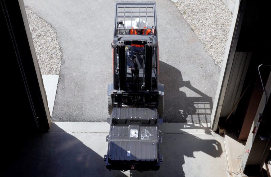
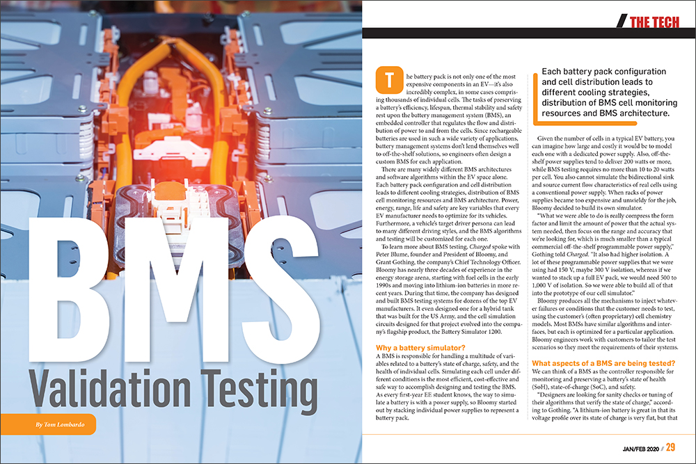
The battery pack is not only one of the most expensive components in an EV—it’s also incredibly complex, in some cases comprising thousands of individual cells. The tasks of preserving a battery’s efficiency, lifespan, thermal stability and safety rest upon the battery management system (BMS), an embedded controller that regulates the flow and distribution of power to and from the cells. Since rechargeable batteries are used in such a wide variety of applications, battery management systems don’t lend themselves well to off-the-shelf solutions, so engineers often design a custom BMS for each application.
There are many widely different BMS architectures and software algorithms within the EV space alone. Each battery pack configuration and cell distribution leads to different cooling strategies, distribution of BMS cell monitoring resources and BMS architecture. Power, energy, range, life and safety are key variables that every EV manufacturer needs to optimize for its vehicles. Furthermore, a vehicle’s target driver persona can lead to many different driving styles, and the BMS algorithms and testing will be customized for each one.
To learn more about BMS testing, Charged spoke with Peter Blume, founder and President of Bloomy, and Grant Gothing, the company’s Chief Technology Officer. Bloomy has nearly three decades of experience in the energy storage arena, starting with fuel cells in the early 1990s and moving into lithium-ion batteries in more recent years. During that time, the company has designed and built BMS testing systems for dozens of the top EV manufacturers. It even designed one for a hybrid tank that was built for the US Army, and the cell simulation circuits designed for that project evolved into the company’s flagship product, the Battery Simulator 1200.
Why a battery simulator?
A BMS is responsible for handling a multitude of variables related to a battery’s state of charge, safety, and the health of individual cells. Simulating each cell under different conditions is the most efficient, cost-effective and safe way to accomplish designing and testing the BMS. As every first-year EE student knows, the way to simulate a battery is with a power supply, so Bloomy started out by stacking individual power supplies to represent a battery pack.
Given the number of cells in a typical EV battery, you can imagine how large and costly it would be to model each one with a dedicated power supply. Also, off-the-shelf power supplies tend to deliver 200 watts or more, while BMS testing requires no more than 10 to 20 watts per cell. You also cannot simulate the bidirectional sink and source current flow characteristics of real cells using a conventional power supply. When racks of power supplies became too expensive and unwieldy for the job, Bloomy decided to build its own simulator.
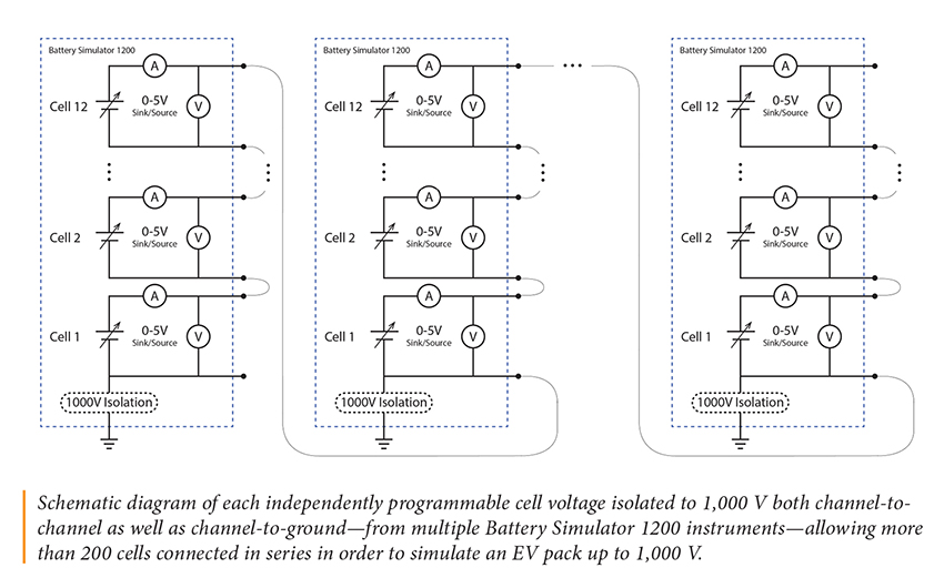
“What we were able to do is really compress the form factor and limit the amount of power that the actual system needed, then focus on the range and accuracy that we’re looking for, which is much smaller than a typical commercial off-the-shelf programmable power supply,” Gothing told Charged. “It also had higher isolation. A lot of these programmable power supplies that we were using had 150 V, maybe 300 V isolation, whereas if we wanted to stack up a full EV pack, we would need 500 to 1,000 V of isolation. So we were able to build all of that into the prototype of our cell simulator.”
Bloomy produces all the mechanisms to inject whatever failures or conditions that the customer needs to test, using the customer’s (often proprietary) cell chemistry models. Most BMSs have similar algorithms and interfaces, but each is optimized for a particular application. Bloomy engineers work with customers to tailor the test scenarios so they meet the requirements of their systems.
What aspects of a BMS are being tested?
We can think of a BMS as the controller responsible for monitoring and preserving a battery’s state of health (SoH), state-of-charge (SoC), and safety.
“Designers are looking for sanity checks or tuning of their algorithms that verify the state of charge,” according to Gothing. “A lithium-ion battery is great in that its voltage profile over its state of charge is very flat, but that makes it difficult to predict where it is, especially over time. Our customers are trying to make sure that their BMS accurately predicts the state of charge of a battery over long periods of time. We have a hardware-in-the-loop system that allows us to run models of different cell chemistries, and the customer can then, using our cell stimulators, apply all of the I/O, all of the signals to the BMS to [make it] think that it’s driving along at 60 miles an hour, then clicking into a charging station and sitting overnight, simulating all the things that an EV is doing.”
This is done in a lab setting that’s controllable, repeatable, and inherently safe, with no actual lithium batteries present. This enables BMS manufacturers to tune their algorithms to make sure that the predicted state of charge matches what the modeled cell chemistry says it should be. That allows engineers to produce a more effective BMS geared toward specific needs, and verify that their SoH and SoC algorithms can accurately predict how much life is left in a battery.
On the safety side, a BMS needs to ensure that each cell’s SoC doesn’t go too low or too high, which is dangerous, if not impossible, to simulate with an actual battery pack. “How does the BMS system react to one cell that is way out of whack or a broken wire? How does it handle that? What does it shut down? Maybe they want to be able to do a lifecycle analysis and detect, over time, how degradation can affect their algorithms,” Gothing elaborated. “There are a lot of things that are very difficult and incredibly unsafe to test using physical batteries.”
Due to manufacturing anomalies and slight differences in operating conditions, the cells within a battery don’t charge or discharge in exactly the same way. One especially important responsibility of a BMS is to maintain cell balance to ensure that these variations don’t impact the whole battery pack. A few millivolts here and there might seem small, but with numerous cells in play, minor variations accumulate and become significant over time. Simulation allows engineers to set a particular cell to a certain voltage and see whether the BMS algorithm is responding as expected.
Testing at any scale
Battery pack designers have a variety of testing needs—some want to test each individual cell, some are looking at the battery unit as a whole, and others are somewhere in between. For EV applications, Bloomy says that 24 and 96 cells are the most common configurations requested by its customers.
“If you think of a battery management system, there’s typically a series of cell monitoring units (CMUs) at a smaller level,” Gothing explained. “Maybe there’s 10 or 16 of those—and then those are communicating with the BMS or the battery control unit (BCU—different companies use different nomenclatures). The BCU is kind of interfacing with the vehicle and the rest of the world—the engine control module, high-voltage interlock contactors, heaters, chillers, and all that kind of stuff, whereas the CMUs are sitting and looking at the individual cells. Some of our customers just want to test the BCU and a couple of CMUs, in which case we’ll provide them 24 cells of simulation plus communications and everything to make the high-level BMS think that it’s connected to 16 modules. Some customers want to simulate every single cell but not pull them up to the full pack voltage, 800 V. There’s a lot of variety, and it depends on how the battery management system is architected in terms of how you can test it. The common denominator is simulating at least one, and often all, of the modules in the system and simulating all of the I/O, all the signals that go into and out of the modules and the BMS to make it think it’s running in the real world, and be able to inject edge conditions and see how it reacts.”
Temperature monitoring
Bloomy battery HIL simulators use a cell chemistry model that takes into account the initial state of charge, cell capacity, ambient temperature and other variables. Those factors are combined with the overall simulated pack current—the amount being sent to the motors—while engineers vary the pack current and outside temperature. The models then generate outputs for cell voltage, expected state of charge and temperature. Those outputs, specifically the pack voltage and temperatures, are injected into the circuit board so it sees all of those conditions as if it were in an actual vehicle.
Bloomy said that some engineers provide a chemistry model that represents a cell with a high effective series resistance, which would cause the unit to generate more heat. The module with a defective cell is then run through an acceleration profile followed by a charging profile, which shows how the BMS responds to the increased cell temperature. Engineers examine the test results and determine whether the BMS is functioning properly, or if it needs changes to its hardware, software, or both. “Hardware is done through a validation kind of phase, what we would call non-real-time,” Gothing told us. “You’re setting I/O and making sure the hardware turns on and turns off appropriately. The real-time side of things, the running of models, is more of an algorithm-tuning exercise.”
Custom battery management systems
Although EV battery makers comprise the bulk of Bloomy’s customer base, the company also works with clients who make drones, robotics, power tools, renewable energy storage systems and other battery applications. So why do so many manufacturers create their own BMS, instead of seeking out an off-the-shelf solution?
“People make a BMS to optimize performance for a particular set of conditions,” explained Gothing. “Those conditions could be the vehicle, the vehicle dynamics, the motors that are being used on it, the weight of the vehicle, all of those kinds of things. The optimization of those things could mean the difference between a vehicle range of 200 and 250 miles. If you compare that to a power tool, the difference between a drill battery that lasts two hours versus two and a half hours, that is not as compelling as an EV [application]. So the BMS design depends on the exact features you want to optimize for, and that is highly customized.”
Bloomy’s flagship product
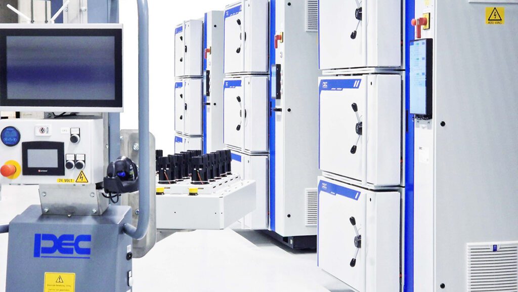
Bloomy offers a comprehensive range of BMS automated testing equipment spanning R&D, validation and production. The heart of all of Bloomy’s BMS testing equipment is the Battery Simulator 1200, but cell simulation is only one part of the complete system. “We use National Instruments (NI) products mostly to simulate the I/O associated with the rest of the world,” Gothing explained. “Simulating pack currents, thermistor values, contactor loads, CAN or isoSPI communication—essentially all the interfaces to make the BMS think that it’s driving along. We use instrumentation, typically NI PXI instrumentation, along with our battery simulators to simulate all of this real-world I/O. And then we run models in a NI software environment called VeriStand, which is essentially a real-time engine for hardware-in-the-loop closed-loop testing. That allows us to run models like a Mathworks Simulink model to control I/O, handle communications, do everything in a fast 400 Hz or 1,000 Hz loop to continuously pretend to be the real world. From there we develop test scripts, user interfaces and reporting mechanisms, so that customers can automatically run through an Excel file of pack currents and see how the system runs or how the BMS responds. While it’s running that, they can manually set a single cell high and see how the BMS responds, run test scripts that go through and verify that every single cell can balance appropriately, validate at what voltage each cell will balance at, and see what variations there are from cell-to-cell measurements on the BMS.”
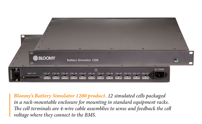
Some of Bloomy’s customers purchase an entire turnkey system, which includes the Battery Simulator 1200 (BS1200) instruments, integrated with Bloomy’s Battery Fault Insertion Units (FIU), software templates for configuring common BMS tests and the NI hardware and software. Others purchase the BS1200 with soft front panel executable software and driver software as an off-the-shelf stand-alone product.
The company recently released Version 3 of its software, which allows customers to control and configure cell simulators from PCs, controller area networks (CANs) and other Ethernet-based systems. “The updates give the customer complete control over the battery simulator,” said Gothing. “It also allows them to combine multiple BS1200 instruments and control them at the same time. Previously our soft front panel would really only let you address one set of up to 12 cells and one of our instruments at a time. The new software allows you to address any number of Battery Simulator 1200 instruments at the same time from the same computer by just selecting which instrument you’re talking to. It has a graphical interface showing the current state of the 12 cells, and you can command the voltages and current limits individually for each cell. In addition, there’s now access to all of the auxiliary I/O for simulating temperatures, and it has analog outputs, voltages, and other types of functionality.”
Once a BMS passes all simulated tests, the manufacturer will conduct field testing on battery packs in a prototype EV on a test track. Bloomy isn’t directly involved in that part of the process. There is, however, a feedback loop whereby the client gathers data from real-world testing, injects the conditions into the simulator, and compares the simulated result with the field-tested result. “This is very powerful!” said Blume. “Engineers are able to simulate test track conditions including environmental conditions and custom drive cycles on our BMS testing equipment in their lab, and actually reproduce the same anomalies and issues that were observed on the test track.”
In addition to BMS validation, Bloomy offers simulators that test a variety of electronic controls and mechanical actuators in the transportation, aerospace, and defense industries, including complex avionics such as flight control computers and full-authority digital engine controls.
This article appeared in Charged Issue 47 – January/February 2020 – Subscribe now.