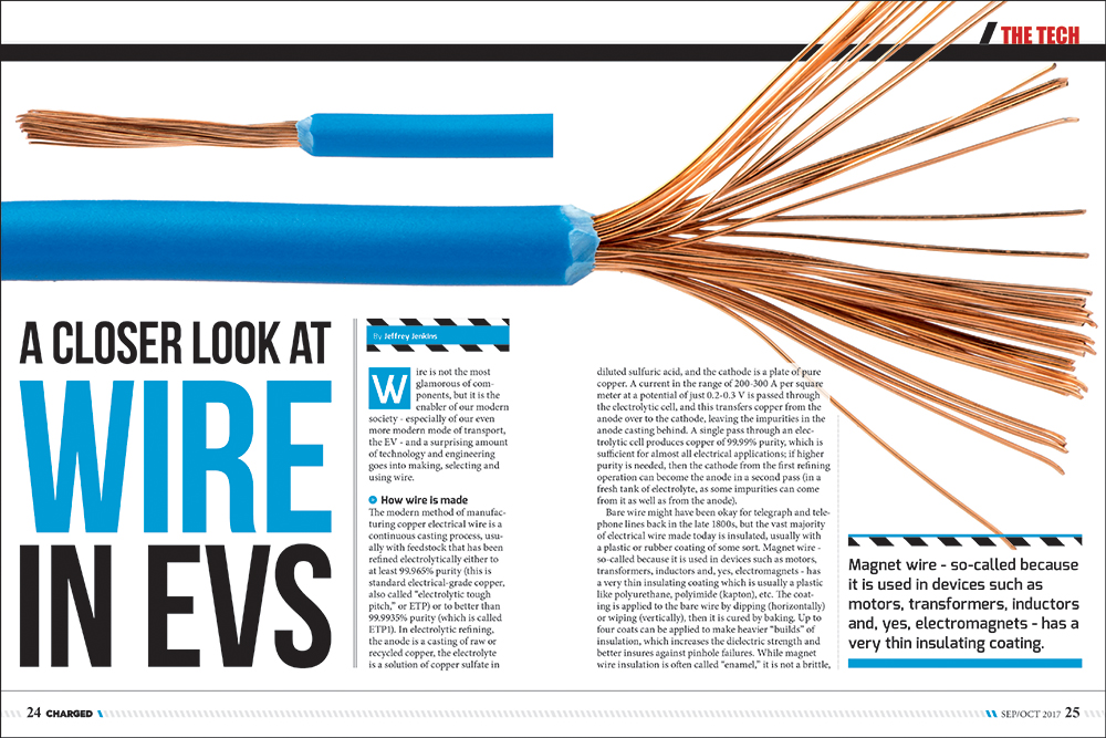
Wire is not the most glamorous of components, but it is the enabler of our modern society – especially of our even more modern mode of transport, the EV – and a surprising amount of technology and engineering goes into making, selecting and using wire.
How wire is made
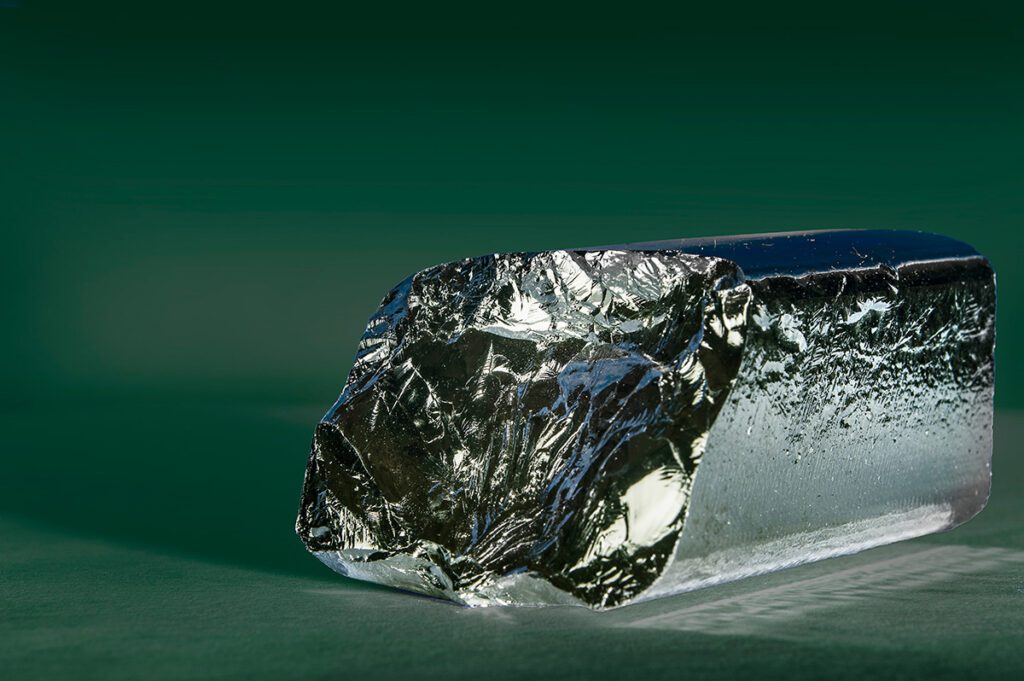
The modern method of manufacturing copper electrical wire is a continuous casting process, usually with feedstock that has been refined electrolytically either to at least 99.965% purity (this is standard electrical-grade copper, also called “electrolytic tough pitch,” or ETP) or to better than 99.9935% purity (which is called ETP1). In electrolytic refining, the anode is a casting of raw or recycled copper, the electrolyte is a solution of copper sulfate in diluted sulfuric acid, and the cathode is a plate of pure copper. A current in the range of 200-300 A per square meter at a potential of just 0.2-0.3 V is passed through the electrolytic cell, and this transfers copper from the anode over to the cathode, leaving the impurities in the anode casting behind. A single pass through an electrolytic cell produces copper of 99.99% purity, which is sufficient for almost all electrical applications; if higher purity is needed, then the cathode from the first refining operation can become the anode in a second pass (in a fresh tank of electrolyte, as some impurities can come from it as well as from the anode).
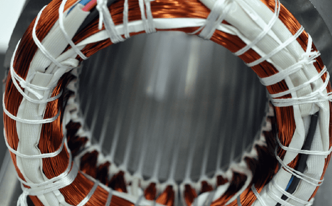
Bare wire might have been okay for telegraph and telephone lines back in the late 1800s, but the vast majority of electrical wire made today is insulated, usually with a plastic or rubber coating of some sort. Magnet wire – so-called because it is used in devices such as motors, transformers, inductors and, yes, electromagnets – has a very thin insulating coating which is usually a plastic like polyurethane, polyimide (kapton), etc. The coating is applied to the bare wire by dipping (horizontally) or wiping (vertically), then it is cured by baking. Up to four coats can be applied to make heavier “builds” of insulation, which increases the dielectric strength and better insures against pinhole failures. While magnet wire insulation is often called “enamel,” it is not a brittle, glass-like coating as is characteristic of a true enamel.
The insulation on most other wires is considerably thicker and even more flexible than the thin coatings of magnet wire; this insulation usually has a much lower temperature rating as well. A common type of magnet wire insulation is good for continuous operation at 130° C, and insulation rated for 180° C doesn’t cost much more. In contrast, most types of general-purpose wire have a PVC insulation rated for 85° C or 90° C, and types rated for 105° C do tend to cost considerably more. The thicker insulation is usually applied by pulling the wire through a heated extrusion die while pellets of plastic or rubber (or a combination of both) are also screw-fed into the die under immense pressure. The pellets melt in the die and flow around the bare wire, resulting in a precise, consistent and relatively thick coating of insulation.
The use and abuse of wire
The wire sold in the electrical department of hardware or automotive stores in the US is typically specified by the type of insulation (for example, GPT is commonly used in automotive applications), the diameter in American Wire Gauge (or just gauge), and the amperage rating (or ampacity). The term ampacity is a gross oversimplification, because it is a function not only of the wire diameter (or, more specifically, its cross-sectional area), but also of the ambient temperature, whether the wire is in free air or in a conduit, whether it is alone or bundled together with other current-carrying conductors, the length of the wire run, the temperature rating of the insulation, and even the frequency of the current, if it is AC. For example, the National Electrical Code specifies that a #14 copper wire in free air at a 30° C ambient temperature and with 90° C rated insulation can carry 35 A continuously; with 150° C insulation the ampacity jumps up to 46 A. The fusing current for a bare #14 copper wire is in the range of 150 A to 200 A, so the difference between what the bare wire can carry – theoretically, anyway – and what the NEC allows is mainly due to the properties of the insulation. Another factor to consider, however, is voltage drop. A #14 wire with high-temperature insulation may be able to tolerate passing 46 A, but the load may not appreciate the lower voltage; induction motors are notoriously intolerant of too low a voltage, as this causes them to run at a higher slip, and losses are roughly the same as the slip percentage.
Two other potential sources of heating in wires that carry AC are skin and proximity effects. Both of these effects are the result of induced circulating (or eddy) currents that arise whenever alternating current flows. Skin effect occurs when the eddy currents induced in a wire oppose the flow of electrons in the center of the wire and add to the flow around its perimeter. Proximity effect, as the name implies, is the result of eddy currents induced in nearby conductors, which will concentrate the main current flow in each conductor closer together if they are of opposite polarity, or push the current flows apart if they are of the same polarity. The former situation occurs in, say, the run from a traction battery to an inverter, or from an inverter to a motor, where the forward and return wires are close together and there is a significant AC component to the current present; the latter situation occurs in multiturn windings such as those found in transformers, motors, etc, and can be a vexing problem to deal with in high-frequency magnetic components.
Skin effect is also proportional to frequency, and is usually inconsequential at the AC mains frequencies of 50 or 60 Hz; AC current will penetrate to a depth of 8.5 mm at 60 Hz, so only conductors larger than 17 mm will begin to experience increased AC resistance as a result of skin effect. The high currents in EV traction motor circuits may very well require conductors of this size, however, and many inverters employ some type of third-harmonic injection scheme to better utilize the battery voltage, which means skin effect can’t necessarily be dismissed out of hand.
Proximity effect is a much more complicated loss mechanism, especially when more than two conductors are present and/or the conductors are wound in layers. It can also reinforce or oppose the skin effect; if all of the conductors are carrying current in the same direction (again, the best examples are the windings in motors and transformers) then the proximity effect will tend to force the main current back into the center of each wire (at least in those wires surrounded by other wires – the wires at the periphery will instead have their current flows pushed to their outsides), partially counteracting the skin effect.
Alternative wire technologies
Aluminum wiring is widely used in the US today, but only for higher-current circuits. In the 60s and early 70s, though, entire houses were wired with aluminum, and that lead to a dramatic increase in fires. The Consumer Product Safety Commission (CPSC) eventually determined that poor interconnects between aluminum wiring and outlets, receptacles and such were to blame. In fact, the CPSC found that the risk of fire went up by 55 times if solid aluminum wire was used for branch wiring, and consequently many insurers will deny or void coverage if there is a single solid aluminum wire between the circuit breaker panel and an outlet or other branch load. So it would seem odd that some automotive suppliers are once again pitching the use of aluminum wire, but now in vehicles.
Let’s start with aluminum’s negatives: it has a higher thermal coefficient of expansion than copper, which tends to loosen connections over time; it creeps, or cold flows, when compressed, more than copper does, which also results in loose connections – particularly ones that rely on clamping, such as crimps or the screw terminals on an outlet; aluminum oxide is a good insulator, and forms almost immediately when aluminum is exposed to air, whereas the oxides of copper are conductive and don’t form nearly as easily; it is fairly electronegative on the galvanic series, so will also readily corrode when in contact with metals that are more positive by at least 0.15 V than it on the series; it has a fatigue life limit while copper does not, so aluminum cannot withstand as much flexing or vibration.
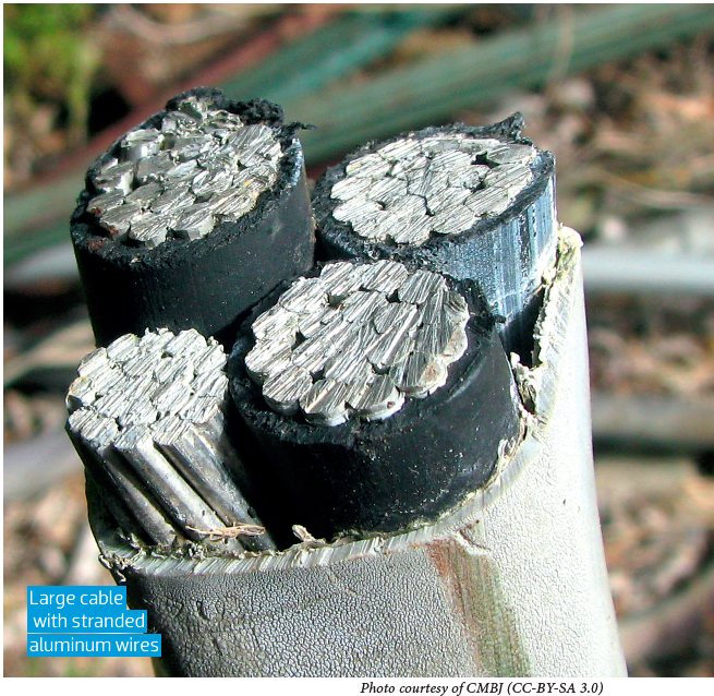
And now aluminum’s positives: it is lighter for the same ampacity as copper, and it is far cheaper than copper on an equivalent ampacity basis as well. That’s it. However, being cheaper and lighter are two very compelling attributes when it comes to vehicles, especially EVs. Aluminum’s downsides can be sidestepped – or at least minimized – through suitable application and termination techniques. For example, aluminum is a good choice for higher-current wires such as those between the traction battery, inverter and motor, whereas it is a terrible choice for low-current or signal-level wires, because of the difficulty of making a good termination and fatigue cracking from vibration/movement.
The termination technique of choice for aluminum wire is welding, but conventional processes like GMAW (aka TIG) are too expensive and/or time-consuming to be employed on an automobile assembly line. Ultrasonic and other friction welding techniques can break through the oxide film without the use of messy flux or expensive shielding gas, joining aluminum wire to a compatible lug very quickly and without heating up the surrounding area. In fact, aluminum has been used for starter and battery cables in ICE vehicles since the early 2000s, mainly in Europe, but if Delphi and other automotive component suppliers have their way, much of the high-current wiring in EVs will soon be made entirely of aluminum as well.
Read more EV Tech Explained articles.
This article originally appeared in Charged Issue 33 – September/October 2017 – Subscribe now.