

Plastic film capacitors relentlessly continue to take over many of the duties in EV power electronics that were once performed by the venerable aluminum electrolytic type, mainly because film capacitors exhibit much lower losses and have a much longer operational lifespan, especially at ambient temperatures in the 75-85° C range. The tradeoff is that film capacitors pack a much lower amount of capacitance into a given volume, but this is rarely a disadvantage in an EV because the energy source is already DC as it comes from the traction battery, and a battery acts very much like a high-value capacitor. That isn’t to say there are no downsides to film capacitors; indeed, there is one exceptionally insidious issue which will be addressed herein.
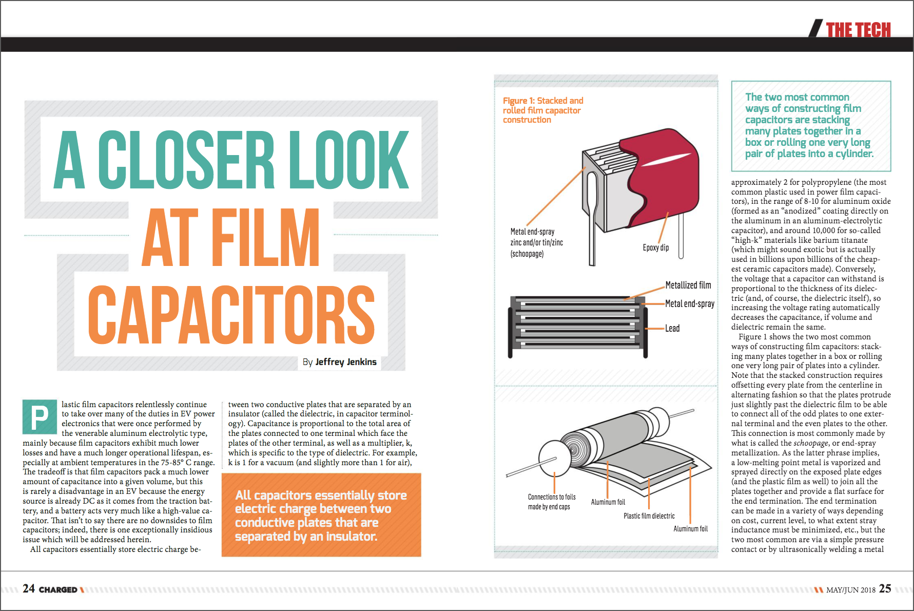
All capacitors essentially store electric charge between two conductive plates that are separated by an insulator (called the dielectric, in capacitor terminology). Capacitance is proportional to the total area of the plates connected to one terminal which face the plates of the other terminal, as well as a multiplier, k, which is specific to the type of dielectric. For example, k is 1 for a vacuum (and slightly more than 1 for air),approximately 2 for polypropylene (the most common plastic used in power film capacitors), in the range of 8-10 for aluminum oxide (formed as an “anodized” coating directly on the aluminum in an aluminum-electrolytic capacitor), and around 10,000 for so-called “high-k” materials like barium titanate (which might sound exotic but is actually used in billions upon billions of the cheapest ceramic capacitors made). Conversely, the voltage that a capacitor can withstand is proportional to the thickness of its dielectric (and, of course, the dielectric itself), so increasing the voltage rating automatically decreases the capacitance, if volume and dielectric remain the same.
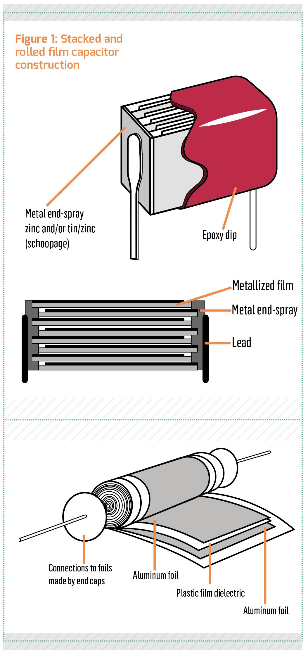
Figure 1 shows the two most common ways of constructing film capacitors: stacking many plates together in a box or rolling one very long pair of plates into a cylinder. Note that the stacked construction requires offsetting every plate from the centerline in alternating fashion so that the plates protrude just slightly past the dielectric film to be able to connect all of the odd plates to one external terminal and the even plates to the other. This connection is most commonly made by what is called the schoopage, or end-spray metallization. As the latter phrase implies, a low-melting point metal is vaporized and sprayed directly on the exposed plate edges (and the plastic film as well) to join all the plates together and provide a flat surface for the end termination. The end termination can be made in a variety of ways depending on cost, current level, to what extent stray inductance must be minimized, etc., but the two most common are via a simple pressure contact or by ultrasonically welding a metal wire or strip directly to the schoopage. The two plates in the roll construction do not have to be offset from the lengthwise centerline to connect them to their external termination – a wire or strip can be welded directly to each plate – but doing so affords the same benefits of drastically reduced stray inductance and greatly increased current rating (and is the method shown in Figure 1).
Before the rise of EVs, the vast majority of power electronic components were intended for use with the AC mains. In these applications, AC is typically first rectified to DC, which has significant low-frequency ripple that needs to be smoothed out, especially with single-phase mains. This is a perfect application for aluminum electrolytic capacitors, because they pack the most capacitance*voltage rating into a given volume, even though their ESR (equivalent series resistance) is rather high, and their AC losses higher still.
There is also a component of ripple that is produced by the inverter (or other switchmode power converter) as a result of it drawing pulses of current from the supply every time a semiconductor switch turns on. This pulsating current interacts with all of the stray resistances and inductances present in the supply, the wiring and the filter capacitors to create triangular-shaped high frequency ripple that reflects from the converter/inverter back to the supply. While this reflected ripple is by no means insignificant, far more capacitance is needed to smooth out the mains frequency ripple, because the amount of capacitance to achieve a certain reduction in ripple is inversely proportional to ripple frequency and reflected ripple is a product of the inverter/converter switching, which tends to be much higher than the mains frequency.
The traction battery in an EV supplies pure DC, of course, so the naive engineer might think that only a small amount of input filter capacitance is therefore needed in the inverter, DC-DC converter, etc. to deal with the purely high-frequency ripple that remains. While that is technically true, there will still be just as much reflected ripple from the power converter whether it is supplied by a battery or the rectified mains, and so the ESR of the input filter capacitor will become the prime consideration. As aluminum electrolytics tend to have a much higher ESR for a given volume and capacitance value, choosing one that just meets the capacitance requirement for, say, an EV inverter – rather than also considering the required ripple current rating – is sure to end in disaster (quite literally: the capacitors will explode from excessive internal heating, spraying corrosive electrolyte all over). Thus, electrolytics need to be grossly oversized in capacitance value when used in an EV just to handle the ripple current. Conversely, film capacitors tend to have very low ESR, and some dielectrics like polypropylene (PP), polyphenylene sulfide (PPS) and PTFE (aka Teflon) also exhibit extremely low AC losses. One other dielectric commonly used in film capacitors is polyester (PET), which has about a 50% higher dielectric constant (k) than polypropylene (and so packs more capacitance into the same volume), but its AC losses are also higher than polypropylene by about 25 times! In fact, most power film capacitors use polypropylene as the dielectric, because it combines low cost, excellent electrical performance and a reasonably high temperature rating of 85° C maximum continuous (although some select parts are rated for 105° C).
At this point it might seem that film capacitors are all puppies and rainbows, with only the relatively low capacitance per unit volume as a downside; however, there is indeed a dark side to them, and it is somewhat perverse/paradoxical that the very qualities that make them such an excellent choice in switchmode power converters – very low ESR and AC losses – can actually result in the outright destruction of themselves or other components. The root of the problem is that film capacitors form very high-quality (“Q”) resonant networks with the stray inductance of the supply wiring, and since every wire has inductance, whether it is wanted or not (approximately 10 nH/cm for a conductor in free space), this problem is difficult to avoid (and even more difficult to mitigate).
A resonant tank stores electrical energy by bouncing it back and forth between the capacitor and the inductor with a frequency, Fr, that is inversely proportional to the square root of L*C, and a characteristic impedance, Z, that is proportional to the square root of L/C. If the ratio of circuit resistance over tank impedance, Z/R, (aka Q) is 1 or greater then oscillations will occur, and if Q is much greater than 1 then oscillations will persist for many dozens of cycles and reach a high amplitude. Since the typical tank formed between an input filter capacitor and the supply wiring consists of a relatively high capacitance and a very low inductance, it will generate high peak current (conversely, a tank formed from low capacitance and high inductance will generate high peak voltage). These high circulating currents do no useful work, of course; instead, they heat up the supply wiring and the capacitors, as well as radiating electromagnetic noise that can wreak havoc in nearby circuits (and pretty much guarantee the device will fail its EMC certification test). The magnitude of these currents can be staggering: a locomotive drive system that the author designed experienced circulating currents on its DC bus in the range of 6 kA before mitigation techniques were employed, and this issue was first discovered when 4/0 cables used as a temporary bus overheated so badly that the insulation charred, then shorted out (exciting times!).
As may be inferred from the equation for Q above, the enemy of resonance is resistance, because it dampens out the current sloshing back and forth between the capacitor and inductor (that is, lowers the Q), and so the lowly aluminum electrolytic capacitor with its “too high” ESR is actually all but immune to forming resonant networks with the stray inductance of the traction battery wiring. It is actually possible to reduce or eliminate resonant ringing on the supply bus by merely adding some electrolytic capacitors to the mix. Of course, that negates one of the principle advantages of film capacitors: their much longer operational life. Another mitigation technique is to purposely insert resistance in series with some of the film capacitors, mimicking the high ESR of aluminum electrolytics; this idea may be simple in concept, but it is anything but simple to execute. A more sophisticated approach is a second-order modulation of the inverter/converter PWM duty cycle to cancel out oscillation on the bus (that is, shifting the turn-on time for the switches to coincide with the peaks of the oscillation); this is also quite difficult to pull off, especially if there are multiple high-power switchmode converters on the same bus. Other approaches are a “shunt active filter” (costly, as it basically requires another converter’s worth of parts) and merely inserting a diode in series with the DC bus to each device (which precludes the possibility of bidirectional operation, such as regeneration in an inverter, but is guaranteed to work).
Film capacitors offer such compelling advantages in switchmode power converters, however – especially at the high power level of an EV inverter – that they are here to stay. As more experience is gained in their use, better approaches to mitigating destructive oscillations will no doubt be found. In the meantime, there is definitely promising masters/doctoral thesis material here, so get cracking on those solutions, EEs-of-tomorrow!
Read more EV Tech Explained articles.
This article originally appeared in Charged Issue 37 – May/June 2018 – Subscribe now.