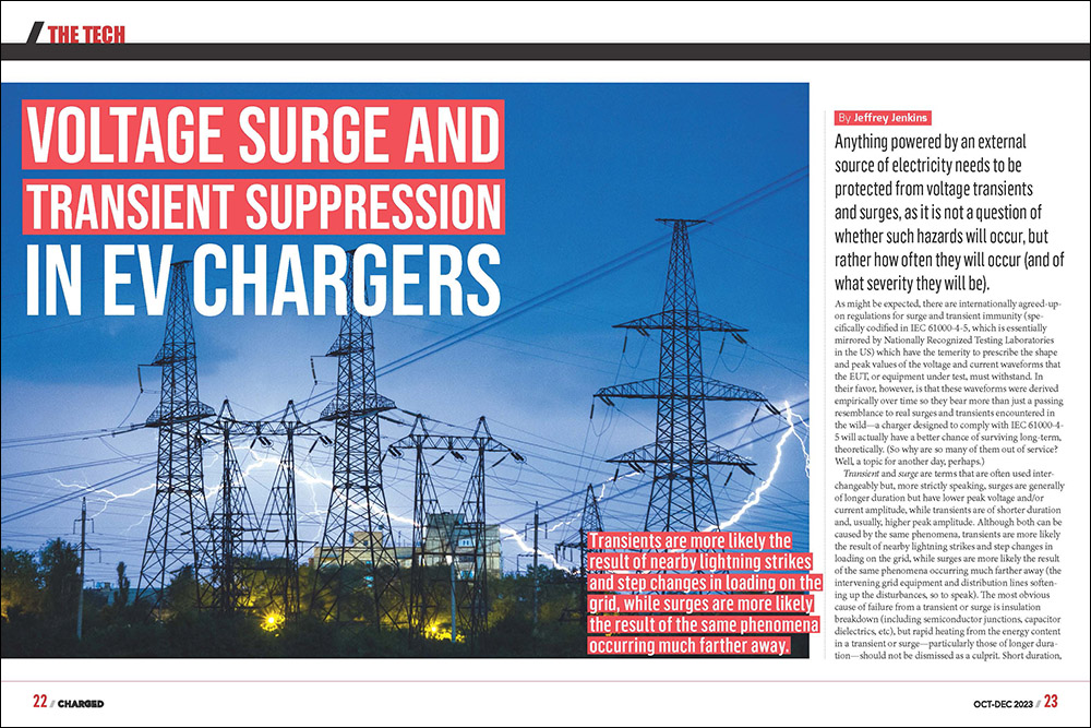
Anything powered by an external source of electricity needs to be protected from voltage transients and surges, as it is not a question of whether such hazards will occur, but rather how often they will occur (and of what severity they will be).
As might be expected, there are internationally agreed-upon regulations for surge and transient immunity (specifically codified in IEC 61000-4-5, which is essentially mirrored by Nationally Recognized Testing Laboratories in the US) which have the temerity to prescribe the shape and peak values of the voltage and current waveforms that the EUT, or equipment under test, must withstand. In their favor, however, is that these waveforms were derived empirically over time so they bear more than just a passing resemblance to real surges and transients encountered in the wild—a charger designed to comply with IEC 61000-4-5 will actually have a better chance of surviving long-term, theoretically. (So why are so many of them out of service? Well, a topic for another day, perhaps.)
Transient and surge are terms that are often used interchangeably but, more strictly speaking, surges are generally of longer duration but have lower peak voltage and/or current amplitude, while transients are of shorter duration and, usually, higher peak amplitude. Although both can be caused by the same phenomena, transients are more likely the result of nearby lightning strikes and step changes in loading on the grid, while surges are more likely the result of the same phenomena occurring much farther away (the intervening grid equipment and distribution lines softening up the disturbances, so to speak).
The most obvious cause of failure from a transient or surge is insulation breakdown (including semiconductor junctions, capacitor dielectrics, etc), but rapid heating from the energy content in a transient or surge—particularly those of longer duration—should not be dismissed as a culprit. Short duration, high-voltage transients with low energy content—something along the lines of a static electricity discharge, let’s say—can create pinhole failures in insulation (especially the silicon dioxide dielectric in integrated circuits) that incrementally increase the chance of total failure later on, while higher-energy transients—such as from an indirect lightning strike or a large motor being disconnected from the grid—can open up major breaches in the insulation and even cause outright arcing, both of which tend to be more immediately fatal. In contrast, surges usually cause equipment failure more from excessive heating in protective components (the irony!) rather than outright dielectric breakdown in capacitors, semiconductors, etc. Regardless, it is the energy content in a transient or surge that ultimately causes failure, and so a surge with a relatively modest peak voltage/current amplitude but which lasts many tens of milliseconds could be just as damaging as a higher peak amplitude transient that only lasts a few tens of microseconds.
Transients are more likely the result of nearby lightning strikes and step changes in loading on the grid, while surges are more likely the result of the same phenomena occurring much farther away.
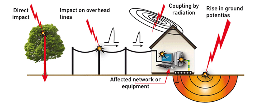
Although it is not practical to fully harden an electronic device against a direct lightning strike with peak amplitudes in the 100s of megavolts and kiloamperes range, the chances of such happening are also vanishingly remote, fortunately (even here in Florida). Lightning more commonly affects the grid indirectly when it strikes some distance away by inducing currents onto all of the distribution lines equally—or in common mode, as compared to between phases or hot and neutral, which is normal mode. Consequently, surge suppression placed between the phase conductors for protection against step load changes won’t do a lick of good against common-mode transients or surges, as they require protective components between the phase conductors (including neutral, if present) and earth ground. Thus, it is necessary to address both common- and normal-mode phenomena separately, especially since the electrical safety regulations that equipment must also comply with limit the amount of leakage current between the phase conductors(s) and ground. This, as we will soon see, can place some serious restrictions on the types of protective components that can be used, especially when the inevitable common-mode filter is factored in for complying with EMC, or ElectroMagnetic Compatibility, requirements (which is itself yet another complicating factor).
Surge suppression placed between the phase conductors for protection against step load changes won’t do a lick of good against common- mode transients or surges
The other common source of transients//surges on the grid is a step change in loading. The most obvious example of this is when a motor is switched on or off. The surge current drawn during turn-on stores energy in the inductance of the distribution network, and this is released once the motor comes up to speed. Other examples are automatic reclosers (the electrical distribution term for a circuit breaker) attempting to re-energize a line that might have been only temporarily overloaded and tap changers on substation transformers that compensate for changes in loading downstream. The vast majority—if not all—of the surges from step changes in load consist of a relatively modest peak voltage (compared to lightning, anyway) but which tend to last for longer periods of time due to the L/R (that is, inductance over resistance) time constants involved.
There are three main ways to deal with transients/surges: blocking, clamping and “crowbarring.” Blocking transients and surges can be accomplished with series inductance and/or shunt capacitance—or a low-pass filter, in other words—and as this happens to describe the common-mode filter ubiquitously employed to meet EMC requirements in anything with a switchmode power converter, said filter is an integral part of the transient protection scheme (whether by intent or accident). The common-mode filter will be far less effective (arguably ineffective, even) against surges, however, and electrical safety requirements limit the amount of shunt capacitance between the phase conductor(s) and ground (to limit the amount of continuous leakage current injected into ground by them), which also limits its potential effectiveness. Furthermore, the insulation on the common-mode filter’s components might not be sufficiently robust to stand up to repeated overvoltage themselves, so it could go from providing protection to needing it.
There are three main ways to deal with transients/surges: blocking, clamping and “crowbarring.”
Clamping and crowbarring are related means of shunting transient/surge energy—which essentially means converting it to heat. The main difference is that a clamp holds steady near its breakdown voltage when conducting, while the voltage across a crowbar drops to a low value once it begins conducting. Clamping devices automatically reset after a surge event, then, but have to withstand extremely high peak wattages (from the product of their high breakdown voltage and the surge current). Crowbar devices can handle much higher surge energy by virtue of their relatively low breakdown voltage—resulting in a lower peak wattage when multiplied by the surge current—but because that breakdown voltage is much lower than the “holdoff” voltage when not conducting, they will not “reset” until the upstream power is interrupted (either by a switch—or, more commonly—a fuse opening up).
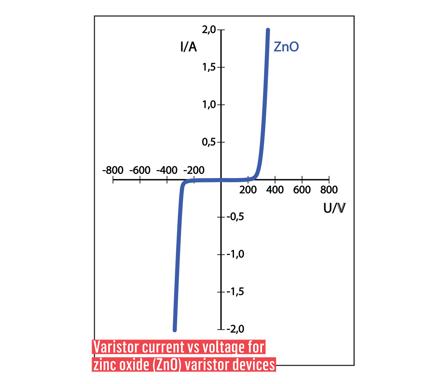
By far the most common component used for protection against transients and surges is the MOV, or Metal Oxide Varistor, mainly because it is both effective and very cheap to manufacture (the cynic in me says the latter is far more important…), as it is basically a compacted chunk of zinc oxide particles. MOVs are clamping devices that don’t (or shouldn’t—more on that below) conduct any current until a certain voltage is exceeded, at which point their effective resistance drops in an attempt (key word, that) to keep the voltage across them constant at the breakdown value. The lower the dynamic resistance during clamping, the closer the clamping voltage will be to the breakdown voltage, and the less instantaneous power dissipated during clamping, all of which adds up to better protection and longer operational life. As these goals are achieved by using a larger volume MOV, however, there is a practical limit to how much optimizing can be done here. Another consideration hinted at earlier is that MOVs have a limited operational lifetime (measured in joules of total energy clamped), because their leakage current increases after each surge event—that is, they do allow some current to pass through them when they should be off, and that current increases each time a MOV is called upon to do its job. Actual end of life occurs when the leakage current is sufficiently high to cause overheating from its continuous power dissipation (rather than the instantaneous dissipation sustained during a surge event), which can be rather more exciting than expected if said overheating results in a fire. One solution is to wire a MOV in series with a crowbar-type device as the latter tend to better block leakage current when not triggered into conduction, while the MOV will automatically reset the crowbar after the surge event has passed.
Another type of clamping device is the Transient Voltage Suppressor diode, or TVS, which is a semiconductor device constructed similarly to a Zener diode, except that it’s optimized for peak current handling rather than the stability of its breakdown voltage. TVS diodes are available in bidirectional versions suitable for use in AC circuits, but they are far more commonly deployed on DC supply lines where their more accurate clamping voltage is a plus and their lower energy rating is not so much of a minus.

Crowbar protective devices include one of the oldest as well as one of the newest technologies: the GDT, Gas Discharge Tube, and the “gateless” thyristor (e.g. SIDACTor by Littelfuse), respectively. The GDT is effectively a spark gap, consisting of two or more electrodes inside a sealed tube. When a sufficiently high voltage is impressed upon any two electrodes, an arc will form, at which point the voltage drop plummets to 30 V or less. This—and the intrinsically robust construction of the GDT—allows it to handle very high peak currents, but one major downside is a relatively slow response time leading to an unpredictable triggering voltage. Consequently, GDTs are rarely used by themselves (notable exception: in the old POTS or Plain Old Telephone System). These shortcomings are addressed in the gateless thyristor, which is a 4-layer (i.e. pnpn) semiconductor device that turns a bug of the conventional gated thyristor into a feature: triggering into conduction when an overvoltage is applied across its main current-carrying terminals. Gateless thyristors are much faster than GDTs, can be designed to trigger at a much lower (and much more consistent) voltage, and exhibit an even lower voltage drop when in conduction (<10 V). On the flip side, they have a far lower peak power (and energy) handling capability from both a unit volume and cost basis compared to a GDT.
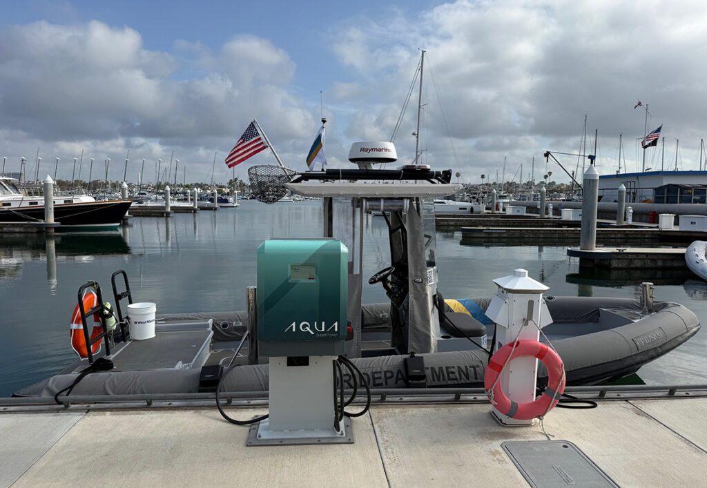
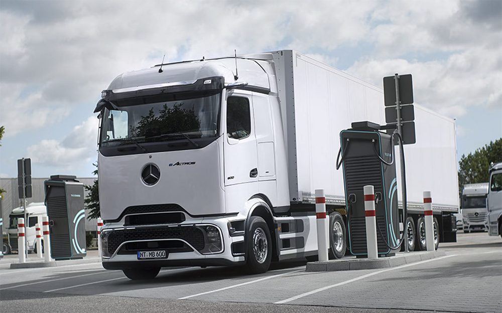
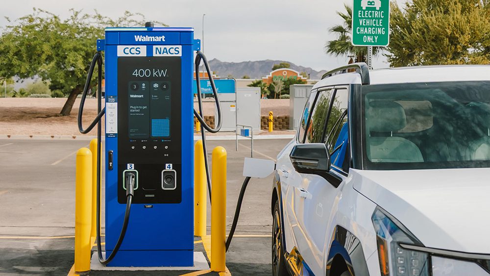
A Level 1 charger plugged into a residential outlet has to meet less stringent conditions than a Level 2 charger wired directly to a breaker panel in a commercial building or a DC fast charger wired directly to a 3-phase distribution transformer.
The last consideration is proximity to the grid (aka “exposure” or “category” level). Closer proximity experiences worsening transient/surge conditions. Thus, a Level 1 charger plugged into a residential outlet has to meet less stringent conditions than a Level 2 charger wired directly to a breaker panel in a commercial building or a DC fast charger wired directly to a 3-phase distribution transformer. In some respects, the higher power handling that typically goes along with closer proximity to the grid naturally affords more immunity to transients and surges, but don’t make the mistake of assuming the same size MOV or GDT, etc, will be up to the challenge everywhere!
This article first appeared in Issue 66: October-December 2023 – Subscribe now.