

Two main types of wireless power transfer systems are being pursued these days: the inductive type, which is magnetically coupled, and resonantly-coupled systems using electromagnetic fields.
The instant availability of maximum torque makes driving even the most economy-oriented EV way more fun than its ICE counterpart, but few would hold the same opinion about the refueling process, especially at fast charge stations with charging cables that rival a Burmese python in size. Wireless charging does do away with wrangling those massive cables, but as regular readers of these articles can probably guess, there are some significant trade-offs involved. Still, it does appear that most of the issues are being addressed, so perhaps this will be the year that wireless EV charging finally hits the mainstream.
Wireless EV chargers are portrayed as cutting-edge technology, but the MagneCharge system made by Hughes (a division of GM at the time) was commercially available on EVs way back in the early 1990s . The MagneCharge system employed a paddle-shaped charging head which contained the primary coil. This was inserted into a mating slot on the vehicle which contained the secondary coil. Though one still had to physically handle a cable, power was transferred across an air gap without any exposed contacts, so this was very much a wireless charging system. More specifically, it was of the magnetically-coupled (aka inductive) type, which is one of the two main types of wireless power transfer systems being pursued these days (the other—to be discussed in much more detail below—utilizes resonant coupling).
An inductive wireless power transfer system consists of (at least) two coils of wire that are usually flat spirals in shape and which are placed in very close proximity and in the same plane and axial orientation. An alternating current supplied to one or more primary coils generates a time-varying magnetic field that induces an alternating current in the secondary coil. If that sounds suspiciously like a transformer to you, that’s because it is—the only difference is that the primary and secondary are physically separated rather than wound on the same core. It should be noted that minimizing the separation between primary and secondary is a major design driver in proper transformers as it maximizes the amount of coupling between the two sides—ergo, the farther the two coils are apart, the lower the amount of power that can be transferred between them. This is sometimes oversimplified as efficiency being inversely proportional to separation distance (air gap), and that isn’t entirely untrue, but it’s more accurate to say that increasing the air gap reduces the amount of power that can be transferred because as the air gap increases, more of the magnetic field lines from the primary only travel in a loop through the air back to itself, without ever intersecting the secondary.
As the separation between the coils increases, more of the energy that would be transmitted by them instead circulates between the power source and the primary’s leakage inductance, doing no useful work.
In transformer terminology, these orphaned loops of magnetic field are called leakage, and they give rise to the dreaded leakage inductance, which will store energy received from the source only to send it back a quarter-cycle later (behaving much like a spring). In other words, as the separation between the coils increases, more of the energy that would be transmitted by them instead circulates between the power source and the primary’s leakage inductance, doing no useful work. If there were no resistance present, then this circulating current would have no effect on efficiency, but in the real (or practical) world there are I2R losses incurred, hence increasing the separation distance does reduce efficiency. One thing to note is that the purely magnetic fields of the inductively-coupled system (as compared to the electromagnetic fields used by the resonantly-coupled system) aren’t blocked by non-magnetic metals like aluminum, copper, etc, but will induce currents in them, and that will lower the overall transfer efficiency. The Hughes MagneCharge system aside, which operated at 6.6 kW (and had a very impressive efficiency for its time of 80%), inductively-coupled wireless power transfer systems are typically used at lower power levels and where a low separation distance (less than a few mm) is easy to maintain, especially when minimizing cost is important, since the coupling mechanism really is no more complicated than two coils which can be treated as a regular transformer from the circuit’s perspective.
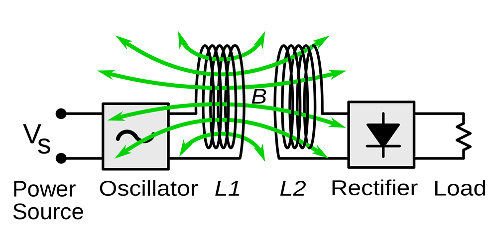
Figure 1: Block diagram of an inductive wireless power system
The Hughes MagneCharge system did have some significant safety advantages over conductive charging interconnects such as J1772, CHAdeMO, etc, but it wasn’t much more convenient to use, as you still had to get out of the EV and physically place the charging paddle into a slotted receptacle on the EV to start charging. Arguably not a big deal if the weather is nice (or the charging station is inside a covered garage), but there’s no denying that merely having to park in a specific (but not too specific) spot then just tapping a button on a phone app or the EV’s user interface to initiate charging would be far more convenient. Such an arrangement with an inductively-coupled system would require an almost Rube Goldberg-like mechanical contraption to bring the two coils close enough together to effect power transfer with reasonable efficiency, and to retract the EV-side coil far enough up in the undercarriage to have sufficient ground clearance to survive potholes, speed bumps and the like while driving.
A system that didn’t require the power transmitting and receiving coils to be brought into such close proximity (and that didn’t require such precise positional alignment of them, too) would make it so that fixed coils could be used on the ground and on the EV, and that is where the resonantly-coupled approach starts to shine. It is tolerant of a much larger air gap between transmitter and receiver (over 100 times larger—tens of cm can be accommodated), is less picky about alignment between the two, and as a bonus, the magnetic field from the transmitting coil will naturally be most attracted to the receiving coil, and will drop to a very low level in the absence of a load on the receiving coil, rather than radiating off into free space in all directions at all times, as is the case with the inductively-coupled approach. What’s not to love about resonant coupling, then? Certainly plenty—and more on why below—but the basic issues are that it’s much more complex and far less tolerant of variations in component value. Despite that, resonant coupling still compares favorably to the mechanical contraptions needed to accommodate inductive coupling at a similar power level (on the premise that electronic complexity is usually less costly to implement than mechanical).
Power transfer will occur using just the magnetic component of the electromagnetic field, and little will be diverted into the electric field.
Power transfer in the resonantly-coupled system uses electromagnetic fields, the same used by a microwave oven, a radio broadcast station, etc, except that the bulk of the energy is transported by the magnetic field component, and the electric field is effectively out of the picture. This is possible because the electric and magnetic fields don’t come together to form a proper electromagnetic field until they have traveled some distance from the antenna. Furthermore, closed loops (like coils) are best at radiating magnetic fields, and are largely ineffective at radiating electric fields (open wires or plates are best for that). Basically, then, as long as the transmitting and receiving coils of the resonantly-coupled system are located within the so-called near field—loosely defined as a distance of 1/6 of a wavelength or less, where the wavelength, in meters, is fMHz / 300—power transfer will occur using just the magnetic component of the electromagnetic field, and little will be diverted into the electric field. While the circuitry involved in the resonantly-coupled system is far more complex than that of its inductive counterpart, the transmitting/receiving coils might not look that different. The main difference is that, in the resonant system, capacitors are added to each coil to form—no prizes for guessing correctly—resonant LC networks (or tanks in the argot) which will naturally oscillate at a frequency (in Hz) of 1 / (2 * Π * (L * C)^0.5) and have a characteristic impedance of (L / C)^0.5.
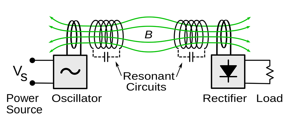
Figure 2: Diagram of the WiTricity resonant inductive wireless power system demonstrated by Marin Soljacic’s MIT team in 2007
Assuming that both LC tanks have fairly similar resonant frequencies (and the separation distance is within the near field), they will preferentially couple to each other rather than to free space, and will generally ignore other non-metallic objects (as with purely magnetic fields). This effectively results in power tunneling directly from the transmitting LC tank to the receiving one in the resonantly-coupled system, rather than radiating off in all directions, as would be the case with the electromagnetic fields of a conventional RF wireless antenna system, or in big loops that follow the same path whether a receiving coil is present or not, as is the case with the purely magnetic fields of the inductively-coupled system.
Another advantage of the resonantly-coupled system over the inductive one is that the LC tanks automatically convert any waveform thrown at them into a pure sine wave, resulting in much lower noise emissions (read: a far easier time getting through EMC compliance testing). And just as LC networks are used to perform soft switching in power converters, they can do the same here, greatly reducing switching losses in both the downstream rectifier as well as the upstream power converter.
So far the resonantly-coupled system doesn’t seem that much more complicated than the inductive one—just add a capacitor across each power transfer coil and call it a day, right?—but there are numerous headaches that come from resonant operation that might have you thinking that the MagneCharge paddle wasn’t such a bad solution after all. First, as already mentioned, real-world inductors and capacitors tend to have much looser tolerances on value, and both (but especially capacitors with any kind of dielectric besides air or vacuum) will drift in value over time and temperature, so there needs to be some means of automatically tracking the actual resonant frequency of each tank. The usual solution here is a phase-locked loop, or PLL, that tries to maintain a peak in sensed voltage (or current) in the LC tank by adjusting the driving frequency. However, it is critical that the frequency adjustment remain on one side of the peak, otherwise the control loop action will invert (i.e. as the peak value decreases, the frequency adjusts to make it worse, rather than correcting it). Second, resonant LC tanks work best at a fixed power level (given by the loaded Q, or the ratio between the load resistance and tank characteristic impedance), as varying the pulse width on the driving side does little to change the power throughput (a side effect of the resonant LC network turning any waveform applied to it into a sine wave), so if the power level needs to change, either the driving frequency has to change or the driving pulses have to be supplied in bursts. Third, bringing the two LC tanks too close together will paradoxically result in them detuning each other! Basically, designing a resonantly-coupled wireless power transfer system that can be mass-reproduced—i.e. made into a real product—is a Herculean feat, and that probably explains why it is taking so long for such products to hit the market, despite the extremely alluring convenience they promise.
Read more EV Tech Explained articles.
This article appeared in Issue 64: April-June 2023 – Subscribe now.