State of the art development for modern electric drives.
By Wayne Petzke, Chief Engineer – Transmission, AVL
Fully electric vehicles (EVs) are here to stay, but this does not come without challenges. EVs will be judged against their combustion engine counterparts for at least the next decade. Discussions with supporters and naysayers of electrified propulsion usually revolve around three main topics: 1) performance, 2) range, and 3) charge time. When developing a vehicle, many people come together to meet a final objective with each engineer trying to optimize their area to best meet the overall vehicle requirements and end-customer wants. While bringing everything together is an interesting conversation, this article will look at just one piece of this very complicated puzzle: the electric drive unit (EDU). EDUs are both simple and complex at the same time when compared to the transmission in a combustion engine powertrain. While they have significantly less parts, this simplicity comes with a different set of challenges.
The largest contributor to the overall mass of an EV is the high voltage battery. Customers want the maximum range between charges without modifying their driving habits. To meet this demand, OEMs find themselves trying to increase electrical storage capacity within the vehicle by installing as many battery cells as possible. Even though battery technology is improving, for a given battery cell and chemistry, this method not only takes up space but also adds mass to the vehicle. At the EDU level we can support mass and size constraints by making it as small and light as possible. However, while reducing the size of the EDU we also need to maximize performance and minimize cost.
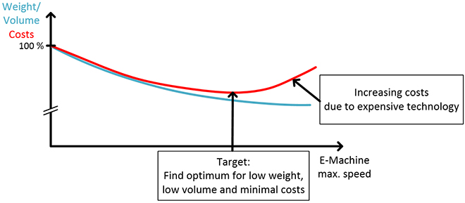
A few years ago, AVL started to investigate ways to reduce the cost of e-machines and discovered an interesting trend. Reducing the size of the e-machine obviously reduces the amount of steel, copper, and magnetic material required to make it, while also potentially reducing its power output. With that in mind, we added e-machine speed to the tradeoff study, due to the relationship of speed and torque with regards to power, and then, the tradeoff curve (Figure 1) was realized. If e-machine speed was increased, we could maintain power but could only reduce the size and materials used to a certain point. When we increased speed the centrifugal forces and resultant loads would also increase and found these loads were manageable up to a certain point without the need for exotic high strength/cost materials. With current materials and manufacturing technology, we found that the optimum point of speed is around 28,000 RPM.
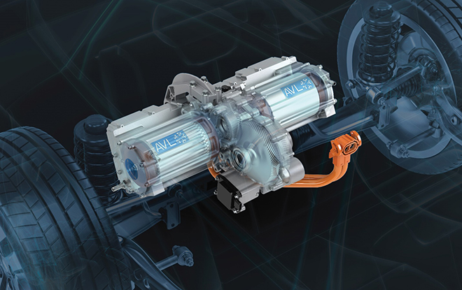
Increasing e-machine speed is a key enabler for increasing power density. Within some boundaries, it can reduce cost on the e-machines active components (rotor and stator), but it raises some areas which require a special focus – bearings, seals, and lubrication. To discuss these items, we will look at one of AVL’s recent R&D projects: the AVL Hummingbird High-Speed E-Axle.
AVL Hummingbird High-Speed E-axle
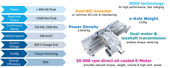
The AVL Hummingbird E-Axle was designed for use in C/D-segment passenger cars and SUVs. The goal of this project was to develop a market leading EDU for these segments that reduced the size and weight, while maintaing performance. To achieve these performance requirments, we leveraged increased e-machine speeds in combination with a numerically higher gear reduction. Peak performance over 400 kW was achieved in testing, however the numerically higher gear reduction was required to make up for the lower torque capability of a smaller diameter motor. As previously mentioned, the bearings on the e-machine were of concern since they have to withstand operational speeds up to 30,000 RPM. By partnering with a bearing manufacturer and deploying AVL advanced simulation methods, we simulated the effects of high rotational speed on off-the-shelf bearings and correlate those back to tests performed by the bearing manufacturer.
Designing bearings to withstand high speeds
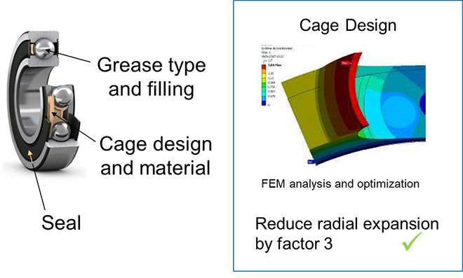
Three key takeaways were identified early in our developments: the bearing cage, bearing lubrication and bearing seals. First, the bearing cage can expand when exposed to increase speeds, thus requiring a design tailored to higher centrifugal forces. Using AVL analysis methodologies, we reduced the radial expansion of the bearing cage by a factor of 3 (Figure 3).
Second, lubrication at higher rotational speeds are quite critical. The Hummingbird E-axle uses a pressurized lubrication system with a scavenging pump to control oil within the gearbox. This was very effective for gear interfaces and bearings further downstream in the gear reduction. However, when the e-machine was operating at a peak RPM, the bearings quickly displaced oil, causing starvation. Working with the bearing manufacturer, we decided to switch the high speed bearings to a sealed grease filled type. To ensure bearing life expectancy, we are continually testing this type of bearing at high-speeds.
The third and final takeaway involves the rotational seals. During our initial development, it was decided to use a non-contact “slinger” style seal on the high-speed components. This method was chosen not only for effeciency reasons but also durability. Initial tests showed the “slinger” style seals did not provide sufficent measures for oil control and often lead to a small amount of oil escaping during operation. Contact seals made of Turcon material have the ability to tolerate high linear velocities. However, they had not been introduced to the market when we began our initial testing and concept development. Now, our current design uses the varilip seal made from Turcon since this seal provided effective sealing and met our performance requirements.
Oil Control within the Gearbox
For the AVL Hummingbird E-Axle, we seperated the gearbox interior area from the e-machine internal area to reduce windage and viscous drag between the stator and rotor. The e-machine uses sealed grease-filled bearings, but the internals of the gearbox, as mentioned above, are pressure fed oil from a scavenging pump. An interesting discovery from our analysis and testing showed that at high speeds any oil collecting in the housing would be atomized into a fine mist. This required oil control features to direct oil off spinning components and return them to the sump. In additon spray jet nozzles, directed at the gear interfaces, were required to place lubrication directly where it is needed and oil fed circuits to the bearings were required.

Using PreonLab, as a particle based 3-dimensional CFD simulation package, AVL carefully analyzed oil flow and surface wetting to develop our oil control strategies. Clear case testing was used to validate our strategies and the only adjustments required during testing were for the orifice sizes in the jet nozzles.
Future of the AVL Hummingbird E-axle
At the end of 2020, AVL installed the Hummingbird E-Axle into a demonstration vehicle and began road testing. Our research and development in high speed e-machines is not complete, as we are continually looking for additional ways to optimize the system and push the boundaries of technology. Visit AVL.com to stay up-to-date on AVL Hummingbird E-Axle technical details for the development of a second generation.
For more information on the AVL Hummingbird E-axle, watch our on-demand presentation on AVL’s holistic approach to developing high-speed e-axles from the ChargedEV Spring Virtual Conference.


