
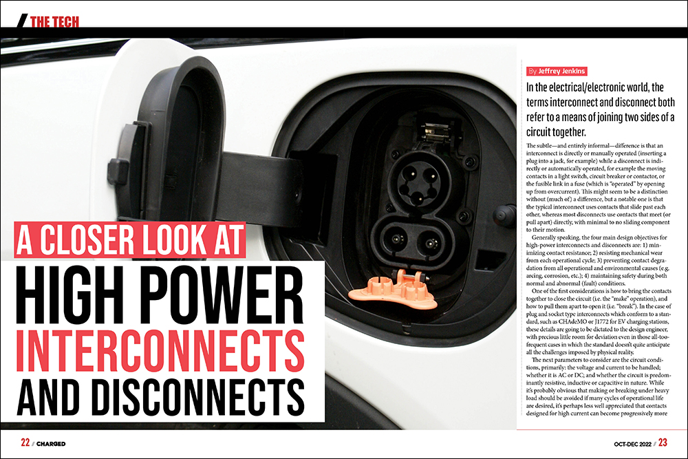
In the electrical/electronic world, the terms interconnect and disconnect both refer to a means of joining two sides of a circuit together. The subtle—and entirely informal—difference is that an interconnect is directly or manually operated (inserting a plug into a jack, for example) while a disconnect is indirectly or automatically operated, for example the moving contacts in a light switch, circuit breaker or contactor, or the fusible link in a fuse (which is “operated” by opening up from overcurrent). This might seem to be a distinction without (much of) a difference, but a notable one is that the typical interconnect uses contacts that slide past each other, whereas most disconnects use contacts that meet (or pull apart) directly, with minimal to no sliding component to their motion.
Generally speaking, the four main design objectives for high-power interconnects and disconnects are: 1) minimizing contact resistance; 2) resisting mechanical wear from each operational cycle; 3) preventing contact degradation from all operational and environmental causes (e.g. arcing, corrosion, etc.); 4) maintaining safety during both normal and abnormal (fault) conditions.
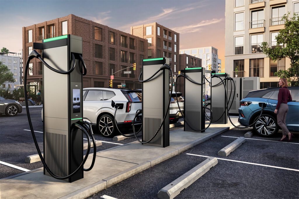
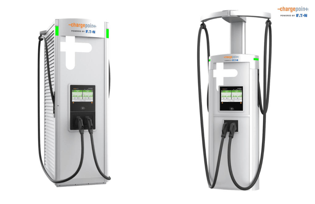
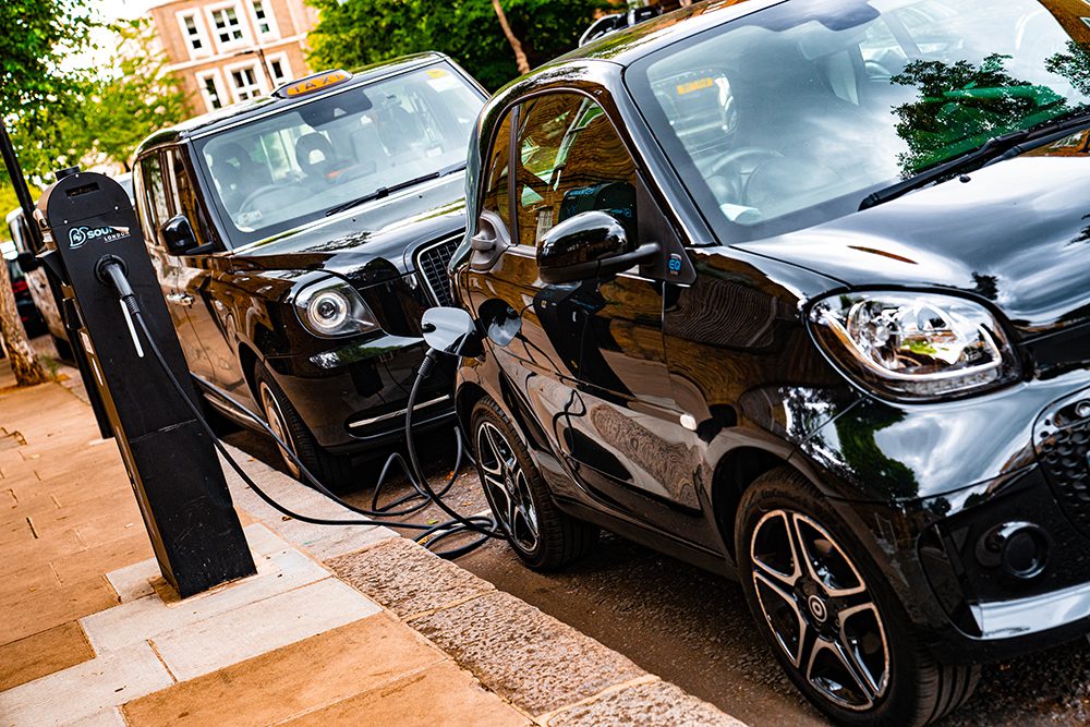
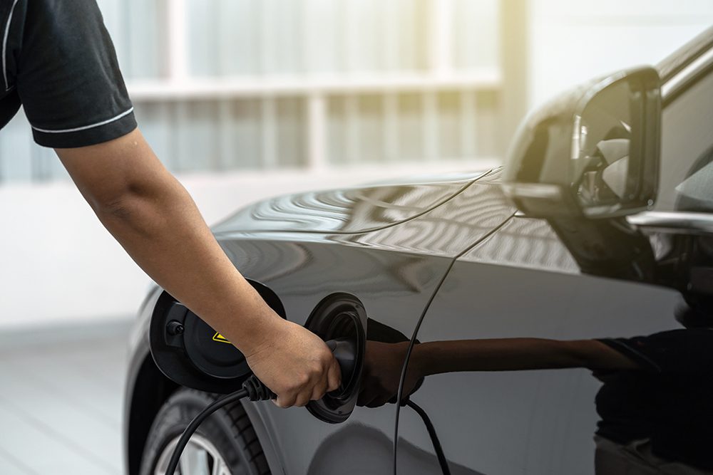
One of the first considerations is how to bring the contacts together to close the circuit (i.e. the “make” operation), and how to pull them apart to open it (i.e. “break”). In the case of plug and socket type interconnects which conform to a standard, such as CHAdeMO or J1772 for EV charging stations, these details are going to be dictated to the design engineer, with precious little room for deviation even in those all-too-frequent cases in which the standard doesn’t quite anticipate all the challenges imposed by physical reality.
It’s perhaps less well appreciated that contacts designed for high current can become progressively more resistive from repeatedly making/breaking under no-load conditions (aka “dry switching”).
The next parameters to consider are the circuit conditions, primarily: the voltage and current to be handled; whether it is AC or DC; and whether the circuit is predominantly resistive, inductive or capacitive in nature. While it’s probably obvious that making or breaking under heavy load should be avoided if many cycles of operational life are desired, it’s perhaps less well appreciated that contacts designed for high current can become progressively more resistive from repeatedly making/breaking under no-load conditions (aka “dry switching”). This is due to the buildup of sulfides and/or oxides on the contact surface, which requires either a sufficient current flow during the make operation to punch through them (read: a sufficient voltage difference), or a strenuous sliding/wiping action, which will itself result in accelerated wear of the contact surfaces (a case in which the cure is arguably as bad as the disease). Otherwise, when circuit conditions are predominantly inductive, it is the break operation that is most stressful, because of the arc that will jump across the opening contacts if it is not suppressed with a snubber of some sort (e.g. a metal oxide varistor, resistor-capacitor circuit, etc.).
Conversely, when circuit conditions are predominantly capacitive—as typically applies to the input to a charger or an inverter—then it is the make operation that is most hazardous, due to the extreme current which will flow if the voltage difference is not reduced with a pre-charge circuit just prior to closing the contacts (with, for example, a smaller relay and resistor wired across the main contacts).
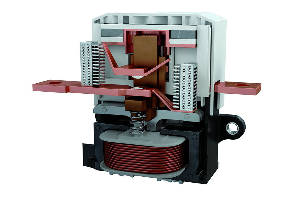
The final circuit condition that greatly affects interconnect/disconnect design is whether AC or DC is being switched. AC of a given power level is far easier to deal with, because the voltage and current periodically cross through zero (e.g. 100/120 times per second for 50/60 Hz, respectively), which will tend to extinguish any arcs that might form during the break operation (there is less benefit to switching AC during the make operation, since it is practically impossible to synchronize the closing of a contactor—much less a human inserting a plug into a socket—with the zero-crossing of the AC voltage waveform). Note, however, that at a high enough voltage and/or with an insufficient contact separation distance (exacerbated by separating the contacts too slowly during the break operation), mains-frequency AC will happily re-strike an arc 100/120 times per second. Two solutions often employed in higher-voltage disconnects are magnetic blowouts, in which magnets placed on either side of the contacts push the arc away as they separate; and filling a sealed contactor with sulfur hexafluoride, a gas with a dielectric strength approximately 2.5 times higher than air (however, it is a potent greenhouse gas—the “no free lunches” rule strikes again).
Two solutions often employed in higher-voltage disconnects are magnetic blowouts and filling a sealed contactor with sulfur hexafluoride, a gas with a dielectric strength approximately 2.5 times higher than air.
As is so often the case in engineering, optimization of one parameter comes at the expense of another, and so it is with electrical life vs mechanical life vs corrosion resistance for the contacts in an interconnect or disconnect. For plug-and-socket interconnects (by far the most common type), the contact surfaces will almost certainly slide past each other during the make/break process, and this is where the heartache of mutually exclusive goals begins. The first pair of contradictory goals is that minimizing the contact resistance requires the contacts in plug and socket to meet with high force, but that then makes the plug too difficult to insert or remove from its mating socket. For plugs/sockets that are only infrequently mated—such as for a dryer or electric range—straight blades in the plug that must force apart curved leaf-spring contacts in the socket are acceptable, despite requiring 10 kg or more of force to mate in the case of dryer and range interconnects.
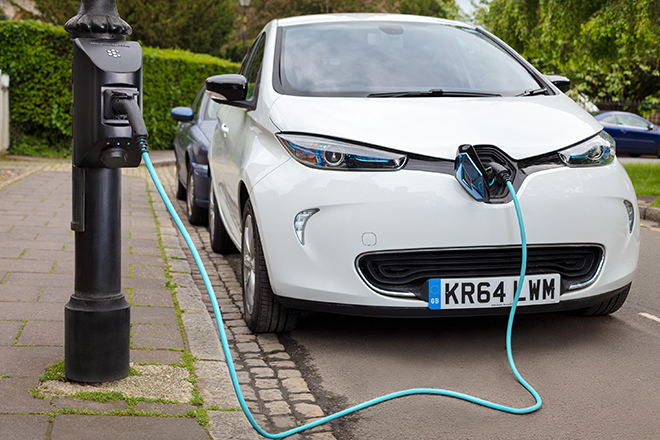
An AC charging station port on an EV handles a similar maximum amount of power to an electric range (i.e. 240 VAC / 50 A), but requiring a similar 40+ pounds of force to insert the plug into its charging port would not be welcomed by any EV owner (to say nothing of the fact that the combo would wear out after 100 or so uses). One practical solution is to use round pins that mate with sockets that are a cylindrical hyperboloid in shape (strongly resembling a “Chinese finger trap”), as this will achieve a much higher total contact area between each pin and socket, while requiring even less insertion/removal force. A cylindrical hyperboloid socket is much more expensive to manufacture, of course, but this is a case in which the less expensive solution—straight blade interconnects—is simply unworkable, rather than merely not as good.
To continue the theme of trade-offs, improving the mechanical and/or corrosion-resistance properties of a contact material tends to come at the expense of lower conductivity, so it is very common to make the contact out of one metal or alloy, and then plate another metal/alloy onto it. For contacts that can be protected from the atmosphere (e.g. inside a sealed contactor), the emphasis can shift from achieving the highest corrosion resistance to minimizing both metal transfer from arcing and contact resistance, but the contacts in the plugs and sockets of EV charging stations must contend with all three requirements: good corrosion resistance; good mechanical fatigue and wear properties; and low contact resistance (albeit with less need to minimize material transfer from arcing…or that should be the case, anyway).
The highest conductivity (aka lowest bulk resistivity) is obtained with silver, of course, but the best corrosion resistance is obtained with the platinum group metals, or gold. While silver can be a good choice of contact material inside of a sealed contactor, or for bolted-together connections (such as bus bars), it too readily forms oxides/sulfides (aka tarnish or patina) if exposed to the atmosphere/pollution, and it is also quite a soft metal in its pure form, so it wears poorly and tends to deform, rather than spring back, from impact, meaning it’s not the best choice, whether contacts come together directly or slide past each other. Alloying silver with copper greatly improves the mechanical properties compared to either pure metal, but then the conductivity drops below that of pure copper (around 92% IACS for sterling silver). Of the platinum group metals, palladium is most commonly used both in alloys and as a plating for contacts, as it has excellent corrosion resistance and decent hardness without being too brittle, making it a preferred choice for sliding contacts. On the minus side, its conductivity is much worse than that of pure copper (16% IACS) and it is exceptionally expensive, of course. Rhodium has better conductivity than palladium (about 38% IACS), and is much harder as well (about 3x to 4x), but that also means it is more brittle, so perhaps it’s an even better choice for sliding contacts, rather than those that meet with considerable impact force.
The final consideration is operational and environmental safety, which mainly consists of not exposing live conductors, if applicable, and not catching on fire due to overload, an external ignition source, arcing, etc. The latter objective can be met by only using materials which are non-combustible and which won’t melt at too low a temperature. Operational safety can be much more difficult to achieve for interconnects that are handled by a person, like the charging plug for an EV fast charger, compared to devices located inside a charger or inverter, such as a contactor or a fuse. A decent—if not foolproof—solution is to simply shield the contacts on the live side of an interconnect in two dimensions (so that sliding along the third axis is still possible). This is the strategy employed by every electrical outlet found in the home, after all, and though it has arguably stood the test of time, it is still possible to stick a foreign object into the outlet terminals, or only partially insert the plug into the outlet, thereby exposing the live circuit to a child’s (or a fool’s) fingers. Consequently, a more thorough solution is to use retractable shutters over the pins, sockets, or both, which automatically retract upon insertion of the plug into its receptacle.
Lastly, the means by which wires are terminated into their respective contacts is critical to overall safety (and efficiency). At low currents, a spring-cage, or “screwless,” clamp is a very reliable solution, as the spring ensures that the wire strands are pressed against the terminal cage despite vibration or cold-flow displacement of the copper. Screw clamps are used at current levels from a few amps up to around 10 or so, because they can apply far more compressive force for a given housing volume. From 10 amps to several hundred, crimping a lug onto a stranded wire cable is the termination of choice, as it has the lowest possible resistance, good resistance to vibration, and good to excellent corrosion resistance. For extra longevity and corrosion resistance, lugs can be filled with dielectric grease before inserting the cable and crimping it. The grease is forced out from every interface between the cable wires and the lug wall, effectively sealing off the crimped area from air, liquids, etc. Much the same would be accomplished by soldering the cable into the lug, but that is never done—at least not for cables that will be subjected to flexing or vibration—because the solder causes embrittlement and fatigue cracking of both itself and the copper wires over time. Definitely not something you want happening to a DC fast charger cable carrying a few hundred amps!
Read more EV Tech Explained articles.
This article appeared in Issue 62: Oct-Dec 2022 – Subscribe now.