Sponsored by EPCOS, a TDK Group Company
By Matt Reynolds, Director of Marketing, Piezo and Protection Devices
The technology behind capacitors has been around since late 1745 when a physicist in Germany found that an electrical charge could be stored by connecting a high-voltage electrostatic generator by a wire to a volume of water in a hand-held glass jar. Although different materials have been used over the years – from glass to paper to ceramics – it wasn’t until the 1950s that Bell Laboratories developed a more reliable and miniaturized low-voltage support capacitor to complement their newly invented transistor. The technology has not changed significantly since until this century.
Due to the continuous development of power electronics and the trend of miniaturization over the past decade – particularly in automotive and industry applications – capacitor technology has had to significantly catch up to meet the demands of electronic components including better reliability, increased efficiency and miniaturization. New DC capacitor technology offers significant advantages over conventional capacitor technologies when it comes to stabilizing and filtering the DC-link circuits of power inverters.
While these type of capacitors are particularly aimed at developers of topologies with new fast-switching IGBT modules, these new capacitors and new technology can enable new ideas in power electronic designs due to low inductive design and the ability to overcome limits in high temperature ranges and power density.
Designing DC-Link Capacitors for Future Power Electronics
During semiconductor switching, DC-link capacitors are part of the commutation loop, which in turn, affects the entire behavior of the design. Historically, different power electronic designs have utilized low-inductive assemblies of semiconductors and DC-link capacitors to minimize voltage overshoot. However, many system designers are working with capacitors with high volume in large commutation loops. Recently, capacitors with high capacitance density and a very low self-inductance have been developed resulting in low inductance in the commutation loop.
In addition, because DC-link capacitors are used to stabilize the DC-link voltage in power converters, minimizing voltage ripple to avoid electrical stress is crucial in order to comply with EMI requirements. New capacitor technology accomplishes this by balancing the difference between the input source and the output load.
While the primary function of DC-link capacitors is to provide energy storage during hold up time, they are often needed to allow fast and efficient switching of the semiconductor by minimizing the required area. Consequently, the DC-link capacitor size determines the package of a motor inverter. A compact or miniaturized DC-link can be created by optimizing the connection with a high current handling capability and a low self-inductance. Stresses including thermal, electric, environmental and mechanical – some of which have been unforeseen due to new designs and size requirements – must be planned for and designed in. Accordingly, advances in DC-link capacitor technologies have to focus on the demands of future power electronics.
Device Characteristic Advances
The latest ceramic capacitor technology uses a lead-lanthanum-zirconate-titanate ceramic (PLZT) dielectric material to overcome an issue with ferroelectric class 2 ceramic materials where capacitance decreases with voltage. This ceramic is optimized for the antiferroelectric state of the capacitor where capacitance increases with voltage. This allows for the highest capacitance values at DC-bus voltage levels and improves the capacitance density at operating voltage levels. It also decreases the equivalent series resistance (ESR) providing efficient operation at high temperatures up to 150°C and high switching frequencies up to several MHz.
Next, since electrical and thermal conductivity directly impacts the properties and arrangement inside the capacitor, the material and design of inner electrodes must be carefully selected based on the desired performance of the capacitor. The use of copper as an inner electrode material allow for more compact and efficient design, while minimizing electrical resistivity in a preferably wide range of temperatures and frequencies. In compact, designs, any additional self-heating of the capacitor and its connection needs to be prevented, and the selection of copper helps to address this.
The Temperature Effect
In fact, the device temperature of a capacitor and its thermal resistance are important factors in the efficiency of a DC-link capacitor over its lifespan and will define and predict the maximum permissible current. While dependent on the ESR and ripple current, produced heat from losses needs to be conducted from the capacitor efficiently, ensuring that the capacitor’s temperature is constant during continuous operation. With this design, high current ratings can be achieved.
Even without a heat sink or any forced air flow across the capacitor, high current ratings can be reached by using state of the art electronic printed circuit boards (PCB) which provides sufficient thermal conductivity to operate the capacitor at high ripple currents. Simple forced cooling can further increase the maximum permissible current by approximately 25 percent.
Some DC-link capacitors, like the TDK CeraLinkTM can handle even more current per capacitance and achieve high current ratings of more than 1 A/µF and exceeds capacitance density and permissible current per capacitor volume of many ceramic-based capacitors.
While each capacitor technology has different benefits and drawbacks for DC-link capacitor miniaturization, ceramic capacitors are the only technology which combines both high capacitance density and high current rating. Aluminum electrolytic capacitors offer high capacitance density which makes them cost effective when there is no need for high current ratings per capacitance. Film capacitors may offer good ratings, but have low capacitance density and perform about the same as aluminum electrolytic capacitors in terms of permissible ripple current per capacitor volume.
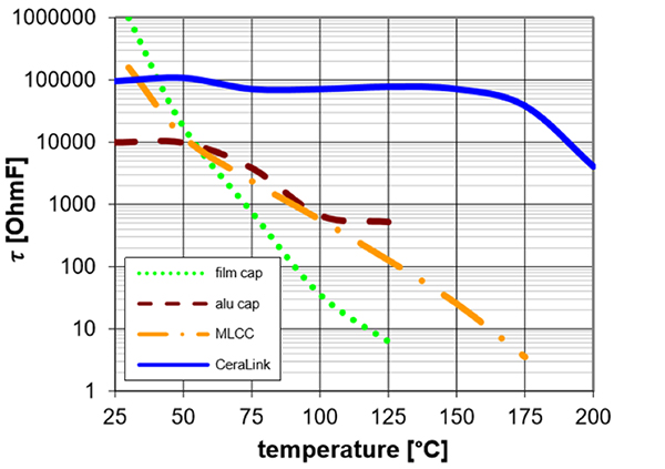
Insulation properties over temperature, capacitors with same voltage rating. The TDK CeraLinkTM PLZT-based ceramic capacitors are compared with two different barium titanate oxide class 2 ceramic MLCC capacitors in a Weibull plot.
Thermal Robustness
Another difference between capacitor technologies is thermal robustness. As a general rule, the leakage current of dielectric materials increases with temperature.
The most widely-used lifetime prediction model refers to the voltage and temperature stress of capacitors. This can be tested through increased voltage and temperature levels. Testing different ceramic capacitors of the same capacitance, voltage and temperature rating show that MLCC capacitors break down early – within tens of minutes.
A recent test shows that all MLCC capacitors failed within 50 minutes, whereas only four out of 30 PLZT-based ceramic capacitors failed during the same timeframe.
With parallel connections of capacitors, the temperature dependency of the capacitance is crucial, where a decrease of capacitance with temperature occurs. If this does not occur, the capacitor with the highest temperature will have the highest capacitance causing the lowest impedance and highest current, increasing the risk of a thermal runaway. High capacitance values are needed at low temperatures, especially in automotive and industry applications that require “cold starts.”
Utilizing DC-link capacitors that employ a negative capacitance characteristic at high temperatures helps to minimize the risk of thermal runaway even when rated temperatures are exceeded. In this model, the hottest capacitor faces the lowest current, providing a stable and self-regulating system against thermal gradients.
Mechanical Robustness Features of DC-Link Capacitors
While the benefits of ceramic capacitors are clear, there is one area that until recently has fallen short and has been a sensitive topic: the mechanical and the thermo-mechanical stress during transport, mounting and operation.
Ceramic materials tend to fail because of cracking due to solder shock or mechanical overload due to the bending of the PCB. Incorporating lead frames into capacitor design can reduce forces on the ceramic due to mechanical-induced stress. Most MLCCs employ a metallic cap on the outer termination to provide a solderable connection. However, temperature shocks from soldering causes cracks in the ceramic that start at the end of the cap and go through the isolation zone into the active area of the ceramic. This can be prevented by omitting the cap and connecting the outer electrode on two opposing surfaces on the ceramic chip.
Conclusion
The advances in power electronics over the past decade including higher power density, efficiency and reliability, has led to new demands on DC-link capacitors. And, as a result, new innovations have been developed to provide a more compact capacitor with high thermal robustness, high current rating and a higher capacitance density.
Low-inductive commutation loops have helped spur some of this innovation by improving the efficiency of semiconductor switching and becoming more important with the increased usage of wide-bandgap semiconductors. New capacitor design helps provide the best thermal stability and very low parasitic influences available in high-efficient or ultra-compact DC-link solutions. Ceramic DC-link capacitors that employ the latest technological advances will be able to face these demands in today’s high-end systems and tomorrow’s future applications.
For more specific product information regarding EPCOS components, please contact Matt Reynolds EPCOS Inc., A TDK Group Company at matt.reynolds@epcos.com or 732-906-4300











































![New York City may replace Central Park’s horse-drawn cabs with electric carriages [Updated]](https://chargedevs.com/wp-content/uploads/2025/09/AdobeStock_273233016.jpg)
