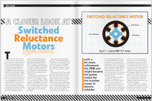
The previous article in this two-part series looked at specialized materials that are (or will be) used in motors; the focus this time will be on the innovative methods of construction that make motors more suitable for EV traction applications. Separating the wheat from the chaff is especially important here, because hyperbole (and outright fantasy) are employed far too often in describing advances in motor technology (second only to batteries, I’d wager). Armed with a suitable dose of skepticism (especially if you see any reference to “overunity,” that is, perpetual motion), let’s look at some intriguing—even promising—advances in the state of the art, starting with the evocative, if unusual-sounding, hairpin winding. But first, a quick review of motor operation and construction.
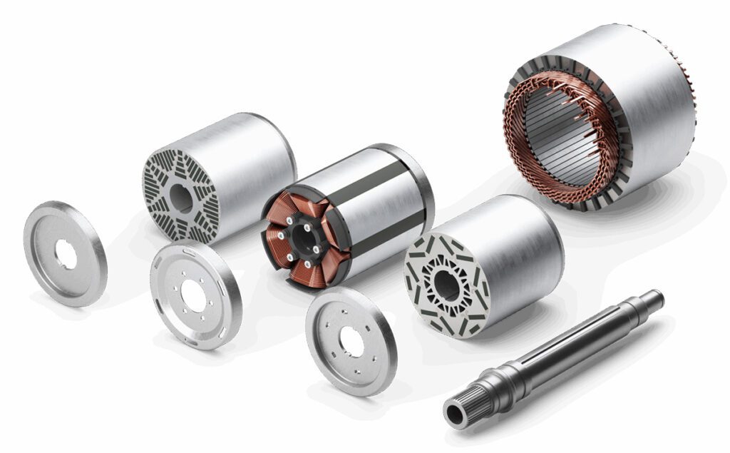
Torque is produced in any motor from the interaction of a fixed magnetic field (“field”) with a rotating one (“armature”). In most AC motors (3-phase induction and synchronous), the rotating part of the motor—the rotor—is where the fixed field is produced, while the stationary part of the motor—the stator—contains the armature, and the apparent rotation of the armature is produced by sequentially energizing pairs of coils—electromagnets—spaced evenly around the perimeter of the stator. The most common arrangement of the armature coils is to place them radially about the inner surface of the motor housing so that their pole faces all point towards the center of the shaft. Unsurprisingly, this arrangement is called a radial flux machine, because the magnetic field produced by the armature coils projects radially towards the rotor/field (an alternate arrangement in which the coils are placed axially will be discussed below; no prizes for guessing what it’s called). There are also two main schemes for winding the coils: concentrated and distributed. The more obvious one is the concentrated winding, in which each coil is wound on its own individual pole face, whereas in a distributed winding construction each coil is spread out over several pole faces. As is usually the case in engineering, one scheme is not clearly superior to the other in all respects. Concentrated windings are less expensive to construct, and exhibit lower losses, while distributed windings produce much smoother torque with less ripple/cogging but incur higher losses because the length of the end turns (that is, the wire not in the slots) has to span multiple slots. In any event, this ground has been well and truly trodden over the last 150 years or so of motor development, so there’s little chance of even an evolutionary improvement here, much less a revolutionary one.
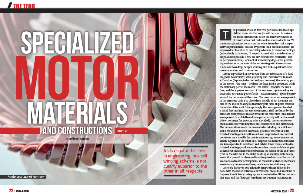
There are, however, two relatively simple things that can be done with the stator coils in a conventional radial flux machine to improve its efficiency: using square wires to better fill the precious slot area; and the “hairpin” winding construction technique, in which half-turns of wire are preformed into a hairpin-like shape to lie precisely in the slots, then welded together to form complete turns. Square wires are much more difficult to work with, because if they twist at all during the winding process—and some twisting is inevitable, really—they can end up lying on the diagonal, which will worsen the slot fill factor, instead of improving it. They are also much more susceptible to insulation failure because of the stress risers which are always produced in fatigue-prone materials which have sharp corners. Preforming the wire into the correct configuration to lie in the slots of the stator—the hairpin winding technique—addresses the twisting issue, and reduces the likelihood of insulation failure because the wire is not being bent under tension as it gets wound around the stator slots, as would occur with a normal coil winding machine. One downside is that the half-turn hairpins have to be welded together to form complete turns, which takes additional time and, most likely, a very expensive laser or electron beam welder to perform. Also, while the welds that join each hairpin together end up outside of the slots, so are in less danger of shorting out, they still need to have an insulating coating re-applied, especially for motors supplied by the typical traction battery voltage in an EV (>300 V).
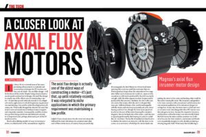
The radial flux machine has served industry well for over a century, but there’s another way of constructing motors that might prove superior in EVs, and that is the axial flux machine. Instead of having a cylindrical rotor inside a larger cylindrical stator, the axial flux machine rotates the pole electromagnets 90° to face a disk-shaped rotor from the side (that is, axially). Construction details start to vary from here, but generally, all the axial flux motors aimed at EVs have a fairly straight flux path through the pole electromagnets, and so can benefit from the use of grain-oriented electrical steel for a couple of percentage points improvement in efficiency. As explained in the previous article, this is not true for the radial flux machine, because the flux paths between stator and rotor are curved.
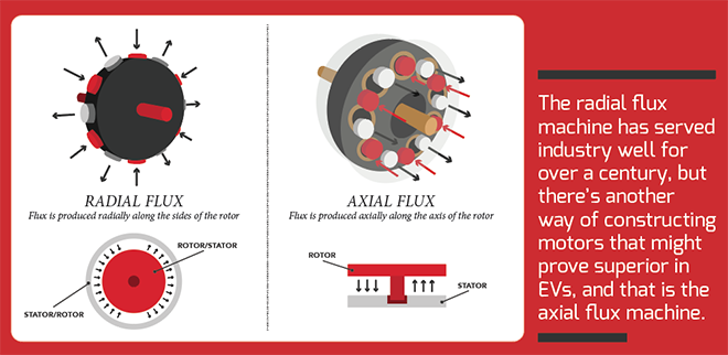
Another benefit of the axial construction—and arguably the most important one—is that the housing and the “back iron”—needed to complete the magnetic circuit between the stator and rotor—are separate. This means the housing of an axial flux machine can be made of aluminum instead of electrical steel, greatly reducing overall weight while enabling much more effective cooling of the pole electromagnets. Furthermore, the pole electromagnets in an axial flux machine don’t add to the outside diameter of the motor, because they are placed within the confines of its rotor, rather than beyond it, as in the radial flux machine. This translates into an automatically longer moment arm between the pole electromagnets and the rotor for a given motor diameter, which means more torque for a given number of ampere * turns of each pole electromagnet (but more back EMF for a given RPM—no free lunches). However, a disk is far less rigid in the axial direction than a cylinder, so making use of the naturally longer moment arm in the axial flux machine requires a very high-strength rotor design, something which is made all the more difficult if magnets need to be embedded within it for the field. Composite materials (e.g. woven fiberglass or carbon fiber cloth impregnated with epoxy) are invariably needed to provide sufficient strength and rigidity without an intolerable increase in the rotating mass, or disturbing the magnetic circuit between stator and rotor from eddy current induction into otherwise non-magnetic metals like aluminum. Composite construction is much more costly both in materials and assembly labor, however, and the pancake-like form factor of the axial flux motor has resulted in very little market penetration so far, much like the oft-promised “wheel motor” (eternally doomed by the huge increase in mass the suspension system has to deal with, as well as the merciless pounding of the shaft bearings).
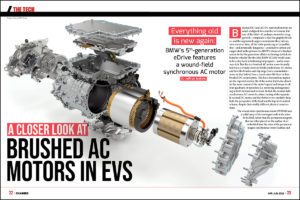
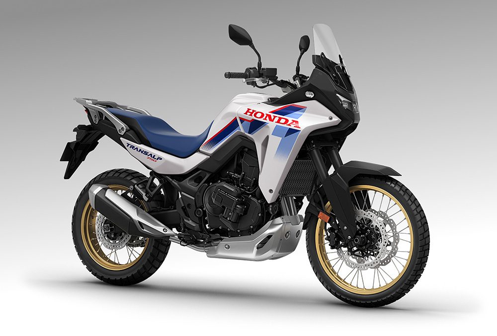
Finally, no discussion of advanced motor construction techniques would be complete without at least touching on the use (and abuse) of permanent magnets, as the PM synchronous motor (PMSM) is still far and away the most popular choice for traction in EVs. As discussed in the previous article, the field magnets in the PMSM are invariably of the rare earth type, and more specifically, of the neodymium-iron-boron (NdFeB) formulation, which delivers the highest field strength and resistance to demagnetization (or “energy product”) at the expense of poor tolerance of high temperatures and an astounding susceptibility to corrosion (requiring protection from oxygen even while being manufactured). Needless to say, both of these downsides can be particularly vexing inside an EV motor that operates outdoors with a hot stator radiating heat from just an air gap away. It is possible to tweak the NdFeB formulation to increase the temperature tolerance, but this invariably reduces the energy product, and at some point the samarium-cobalt (SmCo) formulation will become more attractive (pricing of the raw materials aside—neodymium, samarium and, to a lesser degree, cobalt, are all quite expensive). One construction that helps keep the magnets cooler, and which works well in smaller motors, at least—think e-bikes or, maybe, motorcycles—is the outrunner design. This flips over the roles of the stationary housing and the spinning rotor: the field magnets are placed on the inside perimeter of the housing, which itself spins, so it becomes the rotor, while the stator coils are situated around the former output shaft, which becomes the bearing surface for the spinning housing. This construction technique also solves another vexing problem with the magnets, which is how to keep them from flying off the rotor from centrifugal force (ignoring the tired old internet argument about how there is no such thing). However, the armature is the main heat source in any motor, and the outrunner design buries it in the center with no good way of cooling it, so it seems destined to be relegated to relatively low-power traction applications.
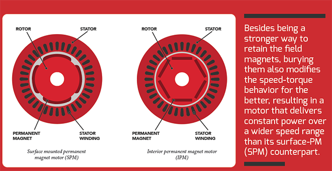
Another way to prevent the magnets in a PM rotor from flying off at speed is to bury them inside it, making what is then called an interior-PM synchronous motor (IPM-SM). Besides being a stronger way to retain the field magnets, burying them also modifies the speed-torque behavior for the better, resulting in a motor that delivers constant power over a wider speed range than its surface-PM (SPM) counterpart. The reason for this is that the magnetic field emanating from an SPM rotor smoothly varies from North to South as each magnet spins past, but the field in an IPM-SM rotor has regions of much stronger intensity where the ends of the buried magnets come closest to the surface, contrasted with regions of very little field intensity near the center of each magnet. The more intense field regions are called “salient poles,” and they interact with the armature to deliver torque in the same manner as in the SPM machine, but the regions of little magnetic field intensity also generate torque because of magnetic reluctance, or the attraction experienced when a magnet (in this case, the stator electromagnet) is brought close to a ferromagnetic material (the steel laminations surrounding the buried magnets in the rotor). The contribution of reluctance torque extends the constant-power speed range all by itself, but burying the field magnets also permits more use of field-weakening, or intentionally timing the current waveforms in the stator to partially counteract the field from the rotor. This reduces torque, of course, but it also reduces back EMF, which would otherwise prevent the inverter from spinning the motor any faster (because the back EMF would then exceed the battery voltage, turning the motor into a generator—this effect is how regenerative braking works, after all). It’s also much safer to apply field-weakening in the IPM motor, because the steel surrounding the magnets will saturate at a lower magnetic field strength than would be needed to demagnetize them, even at their maximum allowed operating temperature. All in all, the IPM design has proven to be a real winner, and has the potential for even more optimization and customization in the future.
Read more EV Tech Explained articles.
This article appeared in Charged Issue 49 – May/June 2020 – Subscribe now.


