An old saw often uttered by an electrical engineer (or their hapless techs) when an electronic device releases its magic smoke goes something like this: “The transistor bravely sacrificed itself to protect the fuse.”
This is a succinct way of saying that conventional fuses (and most types of circuit breakers) shouldn’t be counted on to protect a downstream load from complete destruction in the event of a fault, but only to (hopefully!) prevent a fire from overheated wiring, sparking, etc.
This regrettable shortcoming is mostly due to physics and economics: a conventional fuse or thermal circuit breaker will take about 1,000 to 10,000 times too long to protect most semiconductor devices from overcurrent even when the latter are grossly over-sized (i.e. cost way more than is economically justifiable). Specialized circuit breakers that combine a fast-acting magnetic trip along with the conventional thermal one can allow for less over-sizing of the downstream semiconductors, but they themselves are much more expensive devices, so once again this seems economically questionable.
To truly protect the downstream semiconductor devices from short-circuit faults without suffering from nuisance tripping during normal operating conditions requires an overcurrent protective device that responds to severe overcurrents in 1 to 10 microseconds while still maintaining a more conventional fuse response to moderate overcurrents, which is precisely what an electronic fuse can do—and potentially at a competitive cost to the specialized magnetic-thermal circuit breaker, especially if it allows the use of more rationally-rated semiconductors.
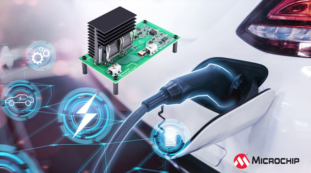
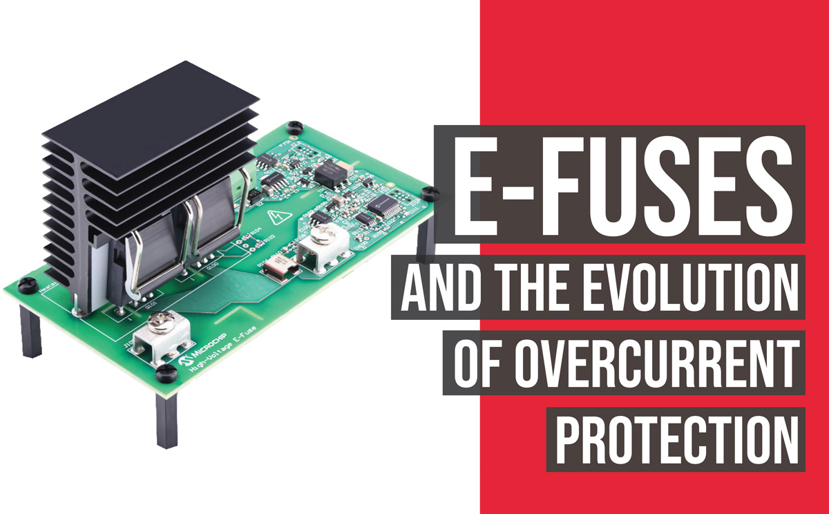
Microchip’s Silicon Carbide E-Fuse demonstrator is available in six variants for 400–800 V battery systems.
To better understand the pros and cons of electronic fuses, a review of conventional fuse and circuit breaker technology is in order. All fuses essentially rely on the melting of a fusible element to break the circuit during overcurrent conditions. The amount of time required is inversely proportional to the degree of overcurrent. Since the heating of the fusible element is the result of I2R losses, a doubling of current should result in a quartering of the time to blow (that is, following a square law). Indeed, fuses are most often characterized by I2t curves as a shorthand way of expressing the energy required to rupture the fusible element by leaving out the resistance, R, in the energy equation of I2R over a given time, t.
E-fuses can not only respond far faster to an overcurrent fault, they can also implement current vs time behaviors that would be impractical (or impossible) with conventional technologies.
Various tricks can be used to modify this current vs time behavior—particularly in lengthening the time that moderate overcurrents can be tolerated without unduly compromising the response to shorts—but at higher overcurrents the amount of time required for a fuse to open tends to an asymptotic minimum (due to the need for the molten metal to actually fall far enough away to break the circuit).
Furthermore, if the fuse must break a DC circuit above 50 V or so, an arc will be developed as the fusible link melts, prolonging the amount of time that current will be allowed through it (albeit with a voltage drop across said arc). This arcing problem becomes increasingly difficult to manage with open-circuit DC voltage (it’s less of an issue for AC, because of the periodic returning to 0 V), to the point that some form of forced arc quenching is required above 300 VDC or so (by surrounding the fusible element with quartz sand, or spring loading it, etc).
Thermal circuit breakers also rely on I2R heating to trip, but this occurs via the heating of a bimetallic strip that causes it to bend. Inexpensive thermal circuit breakers that aren’t expected to trip more than a few times in their operational life will utilize the bimetallic strip directly to move the current-carrying contacts apart (via self-heating of the strip from load current), but more robust designs—and especially at higher currents—will use a separate heater coil around the strip which will itself actuate a toggling mechanism so that there is a snap-action response upon reaching the critical trip temperature, rather than a more gradual movement which would encourage arcing. The toggle mechanism allows for either a bistable action, meaning it is stable in either the closed or open (tripped) positions, or a monostable action, meaning it will automatically return to the closed position after the bimetallic strip has cooled down.
Regardless of the specific design of a thermal circuit breaker, it will suffer from some downsides that don’t afflict the simpler fuse (or not to the same degree, anyway). For one thing, it will take far longer to respond to a severe overload or short-circuit than a fuse of the same nominal current rating. For another, the trip current (or the time delay before tripping occurs) will be more sensitive to the ambient temperature, because the temperature rise needed to operate the bimetallic strip must necessarily be limited so as not to create the very fire hazard it is supposed to prevent.
Thermal-magnetic circuit breakers address the excessive delay in responding to severe overloads that is characteristic of purely thermal circuit breakers by passing the load current through a solenoid—that is, a linear coil of wire around a moving ferromagnetic plunger—which can independently operate the toggling mechanism.
The magnetic force developed by a solenoid is proportional to the current flowing through it, so the higher the load current, the more forcefully (and therefore faster) its plunger will move. The magnetic-hydraulic circuit breaker addresses the sensitivity of trip current to ambient temperature by replacing the bimetallic strip with a viscous fluid that the solenoid plunger must operate against. This preserves the relatively slow response to moderate overloads typical of the thermal circuit breaker with the faster response to short-circuits achieved by the magnetically-actuated mechanism.
The aforementioned shortcomings of conventional fuse and circuit breaker designs can be addressed by going with an electronic solution—that is, by using a semiconductor switch to interrupt the circuit in the event of a fault condition—giving rise to what is popularly called an electronic fuse, or e-fuse for short (though it would be more accurate to describe it as an electronic circuit breaker). E-fuses can not only respond far faster to an overcurrent fault, they can also implement current vs time behaviors that would be impractical (or impossible) with conventional technologies, as well as protect against additional hazards such as overvoltage, over- and under-temperature, etc, at little to no extra cost (i.e. with a few more components or additional lines of code). Furthermore, e-fuses may cost less than conventional electromechanical circuit breakers of similar current interrupt rating (though, admittedly, they compare less favorably to conventional fuses in this regard).
The simplest implementation of an e-fuse is a current-measuring circuit feeding a comparator that controls a semiconductor switch. At operating voltages up to about 50 V and maximum currents up to about 20 A, the current measuring circuit will typically be a resistive shunt that is wired in series with the negative line (aka the low side), whose voltage drop is multiplied by an op-amp-based differential amplifier with a modest amount of gain (2x to 10x is typical here) so as not to incur too high of a power loss in the shunt. At higher voltages and/or currents, a current measuring circuit based on a Hall effect current sensor (or a competing technology, such as giant magnetoresistance) will be more attractive, because there is no I2R loss as incurred by a shunt, and galvanic isolation is automatically provided. Either way, the output of the current-measuring circuit will be compared to a reference voltage by a comparator, which itself can be implemented with an analog IC (such as the venerable LM331 from Texas Instruments), though it’s probably more common to use a microcontroller IC these days, especially if other protective functions are to be implemented. A key requirement for the comparator function is that it have hysteresis, or slightly different turn-on and turn-off thresholds, to prevent oscillation when the load current is near the overcurrent trip point.
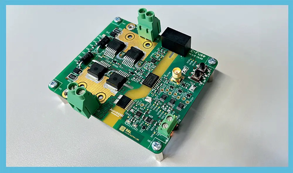
An e-fuse proof of concept for high voltage 800 V automotive applications developed by Asahi Kasei Microdevices Corporation and Silicon Austria Labs GmbH.
The output of the comparator will likely be unable to directly drive the semiconductor switch, so some form of gate driver circuit or IC will be required, but this could merely be a complementary pair of bipolar transistors wired in the classic push-pull configuration. The semiconductor switch is most commonly either a single low-side MOSFET (for blocking current flow in one direction—i.e. only discharge, from the perspective of a battery), or two MOSFETs wired source-to-source (for bidirectional blocking). This latter configuration is commonly used in the BMS for Li-ion batteries (which, after all, incorporates all of the functions of an e-fuse, in addition to its cell monitoring and balancing duties).
A less obvious requirement for the semiconductor switch is that the impedance of the upstream power source not be so low as to make it impossible for the e-fuse’s switch to survive a hard short downstream.
At higher voltages, it is more usual to put the switch in the high side (i.e. the positive line) and use either an isolated or level-shifting gate driver to control it, especially when the negative line must be earth grounded for safety reasons. One key requirement for the semiconductor switch is that it must be able to withstand a higher peak current (or, more correctly, have a higher fusing energy—I2t again) than the device it is protecting; a less obvious requirement is that the impedance of the upstream power source not be so low as to make it impossible for the e-fuse’s switch to survive a hard short downstream.
Note that this latter requirement also applies to conventional circuit breakers and fuses, but is far easier to meet with devices that don’t rely on active semiconductors. This implies that the switch(es) in the e-fuse will be beefier, and therefore more expensive, than the semiconductor devices it is supposed to protect, which would be economically questionable if not for the e-fuse’s extended protection capabilities and much faster response speed.
Finally, e-fuses obviously require power to operate, and if the voltage of the upstream energy source isn’t directly usable by the e-fuse circuitry (in the range of 3 V to 30 V, say) then some type of DC-DC converter will also be needed, adding to the overall cost while decreasing reliability. This also means that an e-fuse can’t directly replace an existing conventional fuse or circuit breaker, as it needs another wire back to the power source to complete its supply circuit (though this is typically easy to retrofit).
It is important to note that there are some power circuit topologies in which no external fuse will be able to protect its semiconductor devices from failure, regardless of fuse technology or how fast it can open. The most common example of such are the switches in a 3-phase inverter, as they are immediately preceded by a capacitor wired directly across the supply rails. This capacitor essentially presents a very low-impedance voltage source to the switches, which means it will deliver a very high peak current to them in the event of a fault such as overlapping conduction of both switches in a bridge leg or a turn-to-turn short in the windings of the motor.
The only good solution for protecting the switches which are directly fed by a voltage source is active current-limiting at the individual switch level (aka pulse-by-pulse current limiting). Another situation in which an e-fuse might fare poorly—especially in comparison to its conventional counterparts—is when subjected to a severe voltage spike, such as from a nearby indirect lightning strike. This is mainly because passive electrical (fuses) or electromechanical (circuit breakers) devices tend to be far more rugged than their electronic counterparts (e-fuses). In conclusion, e-fuses aren’t a panacea, and they won’t save you from bad design decisions and component choices in the power circuits they are supposed to protect, but they could reduce overall warranty and technical support costs, while possibly costing less up front, so they’re definitely worth considering.
This article first appeared in Issue 69: July-September 2024 – Subscribe now.


