


In my very first article for Charged over 10 years ago, I opined that the Switched Reluctance Motor, or SRM, would eventually come to dominate the EV traction market, if for no other reason than the fact that it is almost as cheap as dirt to manufacture. I won’t sprain my shoulder patting myself on the back for a prediction that took 10 years to (partially) come true, but it does seem that the days of the Permanent Magnet Synchronous Motor, or PMSM, and the AC Induction Motor, or ACIM, dominating EV traction applications are coming to a close, with both Toyota and even stalwart ACIM fan Tesla introducing reluctance motors into the mix (albeit not ones that purely employ magnetic reluctance, but more on that below).
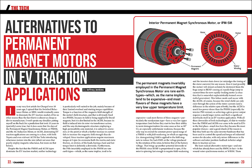
The permanent magnets invariably employed in the Permanent Magnet Synchronous Motor are rare earth types—which, as the name implies, tend to be expensive—and most flavors of these magnets have a very low upper temperature limit.
Despite the fact that the PMSM and ACIM types dominate the EV traction market, neither technology is particularly well-suited to the job, mainly because of their limited overload and starting torque capabilities. Torque is a function of the magnetic field strength of the motor’s field structure, and that is obviously fixed in a PMSM, because its field is being supplied by literal magnets, but it is also limited in the ACIM, because its field is induced into its rotor via transformer action, and like any electromagnetic structure employing a high-permeability core material, it is subject to saturation, or the point at which a further increase in current fails to increase the magnetic field strength thus developed. Since traction applications require maximum torque at 0 rpm (to overcome both the inertia and static friction, or stiction, of the load), having a hard and fast torque limit is definitely a downside. Furthermore, the PMs invariably employed in the PMSM are rare earth types—which, as the name implies, tend to be expensive—and most flavors of these magnets—particularly the neodymium type—have a very low upper temperature limit before they start to lose their ability to resist demagnetization (in some cases as low as 80° C), an especially unfortunate weakness, because the only way to extend the constant power speed range of a PMSM is with field-weakening, in which an opposing (i.e. demagnetizing) field is applied to the field magnets to reduce the back EMF, or the voltage produced by the rotation of the rotor, to below that of the battery voltage.
That brings up another potential downside to the PMSM: since BEMF is proportional to rpm, if the rotor is spinning fast enough to require field-weakening and the inverter shuts down (or misjudges the timing of the stator currents) for any reason, then it (and possibly the motor) will almost certainly be destroyed from the huge jump in BEMF causing an equally huge jump in current from the now rapidly-braking motor (a situation that is somewhat euphemistically termed uncontrolled generation). This failure mode can’t occur with the ACIM, of course, because the rotor’s field can only exist through the action of the stator currents (and a difference in the relative rpm of both), but the ACIM is much less power-dense than the PMSM (especially the interior PM version), so achieving a given power output requires a much larger motor, and that’s a significant drawbacks itself in an EV traction application. With all these downsides of both technologies, it’s fair to wonder how the PMSM and ACIM ever came to be used in EVs in the first place—much less how they became the most popular choices—and a good chunk of the reason is that they both use the same inverter hardware that has been used to control the speed and torque of industrial motors for decades, with only minor differences in the software and rotor position feedback to better adapt them to traction service.
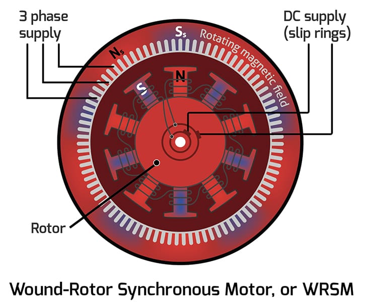
The least-radical alternative motor type—and one which has already been used by BMW, in fact—is the Wound-Rotor Synchronous Motor, or WRSM.
The least-radical alternative motor type—and one which has already been used by BMW, in fact—is the wound-rotor synchronous motor, or WRSM. There is some irony in this, both because supplying current to the rotor requires brushes and a slip ring, which is almost anathema to those EV purists who shun the king of all traction motors, the series field DC type, because of its brushes and commutator (to be fair, the latter wears out far more quickly), but also because it is downright ancient technology, predating even the induction type. Basically, the PMs of the PMSM are replaced by electromagnet coils in the rotor, which means the strength of the field can be directly controlled, something that isn’t possible with fixed-strength permanent magnets, of course. This makes field-weakening to achieve high rpms a non-event, rather than something akin to juggling chainsaws, and makes minimizing the amount of reactive current that would otherwise slosh back and forth between the inverter and motor possible (this current does no useful work, but does use up some of the RMS current rating of the inverter’s semiconductor switches and cause heating from I2R loss).
The downsides to the WRSM are a somewhat lower power density and a higher assembly cost for the rotor (a lower material cost, however, since copper is likely to remain much less expensive than any of the rare earths used in high-strength magnets). Also, of course, the field needs a separate power stage to supply it, and the controller software is a bit more complex, but this is well-established technology, and the WRSM is eminently suitable for 4-quadrant traction applications (i.e. motoring and braking in forward and reverse).
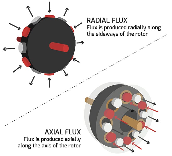
Being able to use the rich ecosystem of existing electronic components, software and knowledge behind every industrial variable frequency drive, or VFD, is a huge advantage that cannot be overstated, and this is no doubt one of the major reasons that the axial-flux variation of the PMSM has received any attention, because it is definitely a contender for the “most expensive way to construct a motor” award. As the name implies, the axial-flux PMSM orients its field magnets parallel to the output shaft on a disc that is sandwiched between the stator phase windings (and the “back iron” to complete the magnetic path, if necessary). This naturally results in a motor with a relatively large diameter-to-length ratio, and since torque is proportional to the square of rotor diameter, but only directly proportional to rotor length, a wide-in-diameter but short-in-length motor—a disc shape—is optimal for high-torque applications, such as EV traction. Securing the field magnets in a disc-shaped rotor requires some form of banding on the circumference of the disc, so it is arguably about as prone to disintegration at high rpm as the surface PM construction, but it is undeniably less effective than burying the magnets, as in the IPM construction. Furthermore, the push and pull of the magnetic fields from the stator poles exert torsional, or wave-like twisting, forces on the axial-flux rotor, and resisting these forces is not the strong suit of a disc shape. Consequently, the parts of the rotor that hold the field magnets in place must have a very high strength-to-weight ratio, which basically means using exotic (read: expensive!) materials like woven carbon fiber composite. The combination of exotic construction materials and rare earth magnets in the rotor is the reason that the axial-flux configuration is one of the most expensive types being considered for EV use, and there doesn’t seem to be much that can be done to lower its cost in the future. For a more in-depth explanation of the axial-flux PMSM construction, see my article in the May/June 2020 issue of Charged. For those wondering if there is an axial-flux analog to the ACIM; well, it’s theoretically possible, but doesn’t really offer any compelling advantages over its conventional radial-flux counterpart.
Another alternative motor construction that leverages the existing VFD ecosystem is the Interior Permanent Magnet-Synchronous Reluctance Motor (IPM-SynRM), which combines the buried magnets of the Interior PM Synchronous Motor (aka IPM-SM) with the rotor structure of the reluctance motor. Basically, the IPM-SynRM behaves pretty much like the IPM-SM as far as the inverter is concerned, but with a significant contribution from reluctance torque (more on what that is below). In both the IPM-SynRM and IPM-SM, burying the rotor magnets also partially shields them from heat as well as demagnetization from the stator (during overloads and field weakening) and also eliminates the risk of being flung off the rotor at high rpm, as is the invariable case for the surface PM construction (that, to be fair, is rarely used in EVs these days). Both Toyota and Tesla have reportedly started using this type of motor, albeit not exclusively.
One crucial difference in the SRM is that the stator electromagnets are supplied with a trapezoidal, but unipolar (DC), current waveform, rather than a bipolar (AC) one.
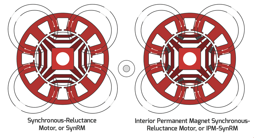
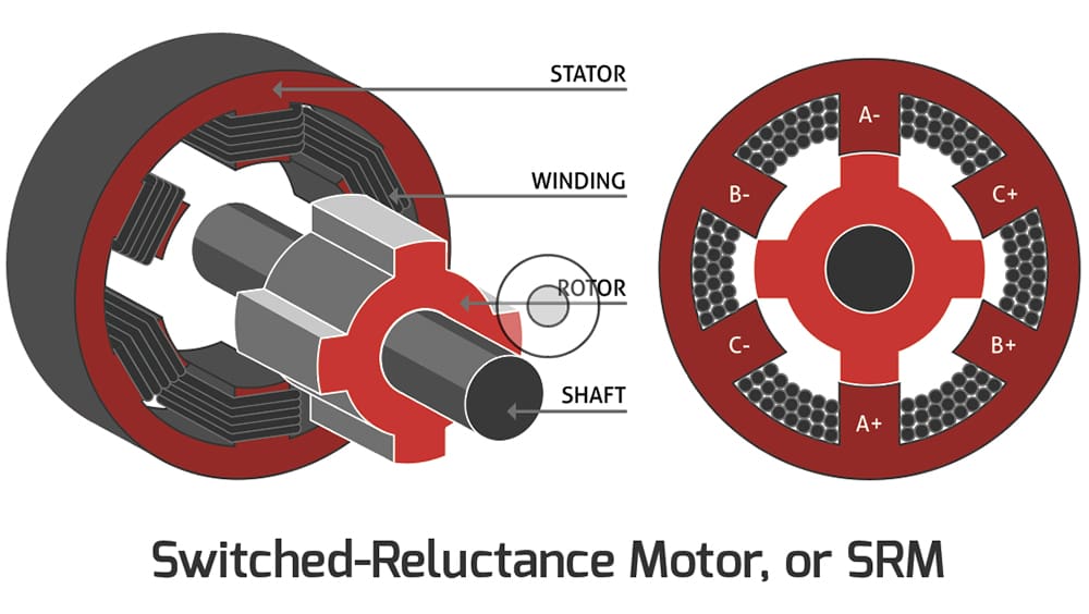
Moving along the continuum from the pure synchronous motor to the IPM-SM, then the IPM-SynRM, we finally come to the pure reluctance motor, which operates only on the attraction between electromagnets in the stator and a magnetically-soft iron or steel rotor. Reluctance is the magnetic analog to resistance, so a magnetic circuit with minimum reluctance occurs when magnetic field lines can freely flow from the North to South poles. This condition occurs in a reluctance motor when a diametrically-opposed pair of electromagnets on the stator align with a matching pair of projecting teeth on the rotor (maximum reluctance occurs when the rotor teeth are between two pairs of stator poles). By constructing the rotor with fewer teeth (or salient poles) than the stator (e.g. 4 rotor poles to 6 stator poles), it can be ensured that when some salient poles are aligned with the stator electromagnets, some will be in between them. Sequentially energizing the stator electromagnets—switching from one pole pair to the next, hence the more common name of Switched Reluctance Motor—will cause the rotor to rotate in much the same fashion as in a PMSM or ACIM. One crucial difference in the SRM, however, is that the stator electromagnets are supplied with a trapezoidal but unipolar (DC) current waveform, rather than a bipolar (AC) one. This means there are no iron losses in the rotor, which is a huge plus, but the torque output has a lot of ripple, and this subjects the rotor to immense tension and compression, which can then cause vibration and noise. It also means that the classic half-bridge power stage used for each phase in an inverter/VFD isn’t the best choice here; rather, a two-switch, two-diode power stage is preferred, as it can rapidly increase the winding current, and just as rapidly decrease it (while recycling any energy still stored in the winding inductance back to the battery).
Another issue that has hampered the adoption of reluctance motors until recently is the fact that the current through the stator electromagnets must be ramped up rapidly and with precise timing as a given rotor pole pair comes into alignment with a stator pole pair, then held at a defined level for a few degrees of rotation, and then rapidly ramped down again as that rotor pole pair rotates out of alignment. This requires very accurate knowledge of the rotor position, which generally means a relatively expensive (and relatively delicate) absolute encoder, and as if that weren’t enough, the inductance of the stator electromagnets increases as a rotor pole pair comes into alignment (because the reluctance drops, and inductance is inversely proportional to reluctance), which makes increasing the current that much more difficult, especially given the fact that the dI/dt (i.e. rate of change in current over time) must be carefully controlled for optimum torque production. This requires a lot of computing power, but fortunately, modern microcontrollers and Field-Programmable Gate Arrays (FPGAs) have more than sufficient grunt for the task. Consequently, the SRM is bound to be the dominant EV traction motor of the future… Any day now, I’m sure…
Read more EV Tech Explained articles.
This article appeared in Issue 63: Jan-Mar 2023 – Subscribe now.