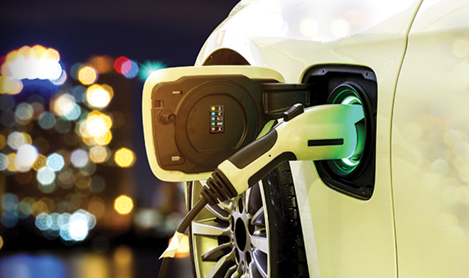
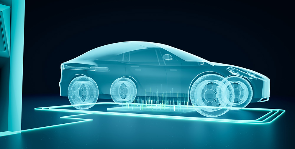
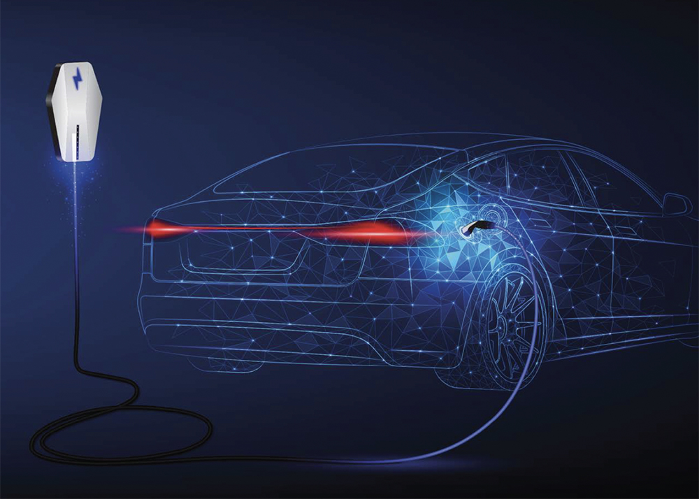
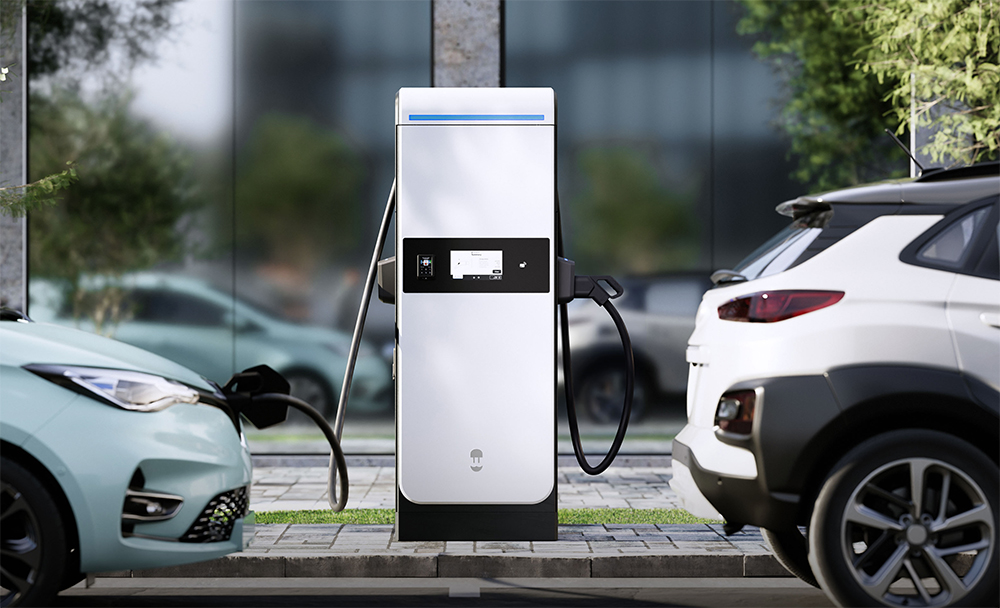
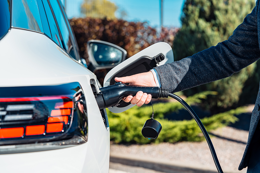
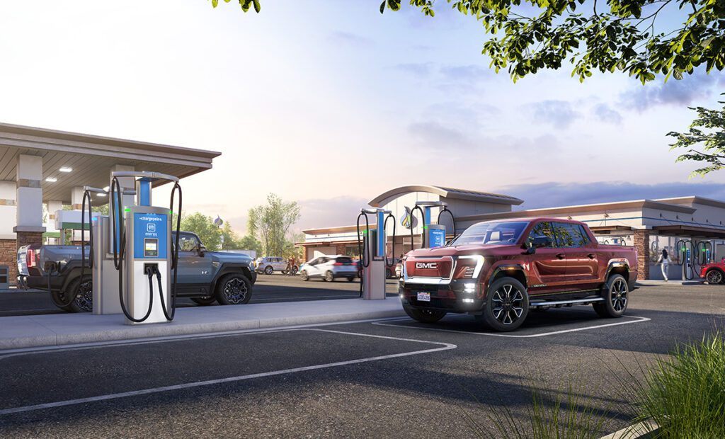
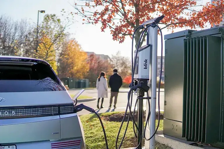
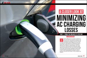
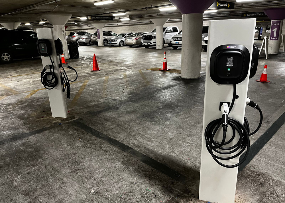
EV charging stations come in many different types and provide differing speeds (or levels) of charge to a vehicle. Most chargers can be classified into one of two types:
- AC chargers, which provide alternating current (AC) power to a vehicle’s on-board charger from an electrical utility supply
- DC chargers, which provide direct current (DC) power to a vehicle’s battery system, bypassing the on-board charger
Some chargers may provide the means to perform AC or DC charging within the same unit. AC and DC chargers are also further classified into sub-types based on the differing levels of power they provide and the type of communication that occurs between the charging station and the vehicle. While they may differ in architecture, EV charging stations must meet three basic goals in order to be a viable solution for keeping EVs running on the road. They must be designed for safety, efficiency and reliability.
This guide provides an overview of the different types of EV charging stations in the market, showing common architectures and how safety, efficiency and reliability are incorporated for the best designs.
AC Charging Stations
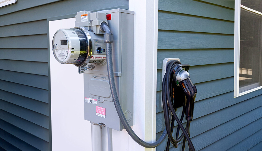
The role of an AC charging station is to safely provide power from the utility supply (grid) into the on-board charger inside of the vehicle. The vehicle’s on-board charger does the conversion of AC power into DC power to charge the vehicle’s battery. Due to space and weight constraints in the vehicle, on-board chargers and AC charging stations are typically limited to lower amounts of power (22 kW or less), which translates to a slow charging time (several hours).
Fuses rated for AC protection serve to limit the amount of short-circuit or overload current that could flow in the event of a fault or failure in the system. Fuses also protect the equipment itself from the risk of fire in the event that wiring and printed circuit boards carry excess current than intended due to the wearing of insulation or corrosion or oxidation on electrical conductors. For convenience and ease of maintenance, some fuses and fuse holders are provided with indicating features to let you know if a fuse has opened and which one has opened.
Earth/ground faults are another risk of electrical shock for users or equipment damage. Exposure to moisture, mis-wiring and degradation of insulation on wiring are just some of the causes for earth/ground faults. Leakage currents to parts of the EV charging system that can be touched by users present a risk of shock if they are not limited to a safe level. Additionally, excessive amounts of leakage currents to earth/ground can cause arcing with enough energy to rupture equipment and potentially damage anything nearby the equipment. Earth/ground-fault relays are devices used to detect these types of faults and signal the need for appropriate action to take place, which often involves disconnection of the power supply.
Outside of safety, equipment performance and reliability are critical for the long-term survival of EV charging stations in outdoor environments. Electrical transients on the AC grid, such as surges due to lightning strikes or voltage fluctuations due to other loads on the electrical grid, tend to be problematic for sensitive electronics in EV charging stations. Overvoltage protection devices, such as metal-oxide varistors (MOVs) and transient voltage suppressor (TVS) diodes, are instrumental in absorbing transient energy from the grid and protecting sensitive systems downstream. Electrostatic discharge (ESD) events are also problematic for some of the “smart” features on AC charging stations, such as user displays with touch screens, communication ports, and antennas for wireless payment and communication systems. TVS diodes and polymer ESD suppressors are often the go-to solutions for reducing the risks related to ESD events.
DC Charging Stations
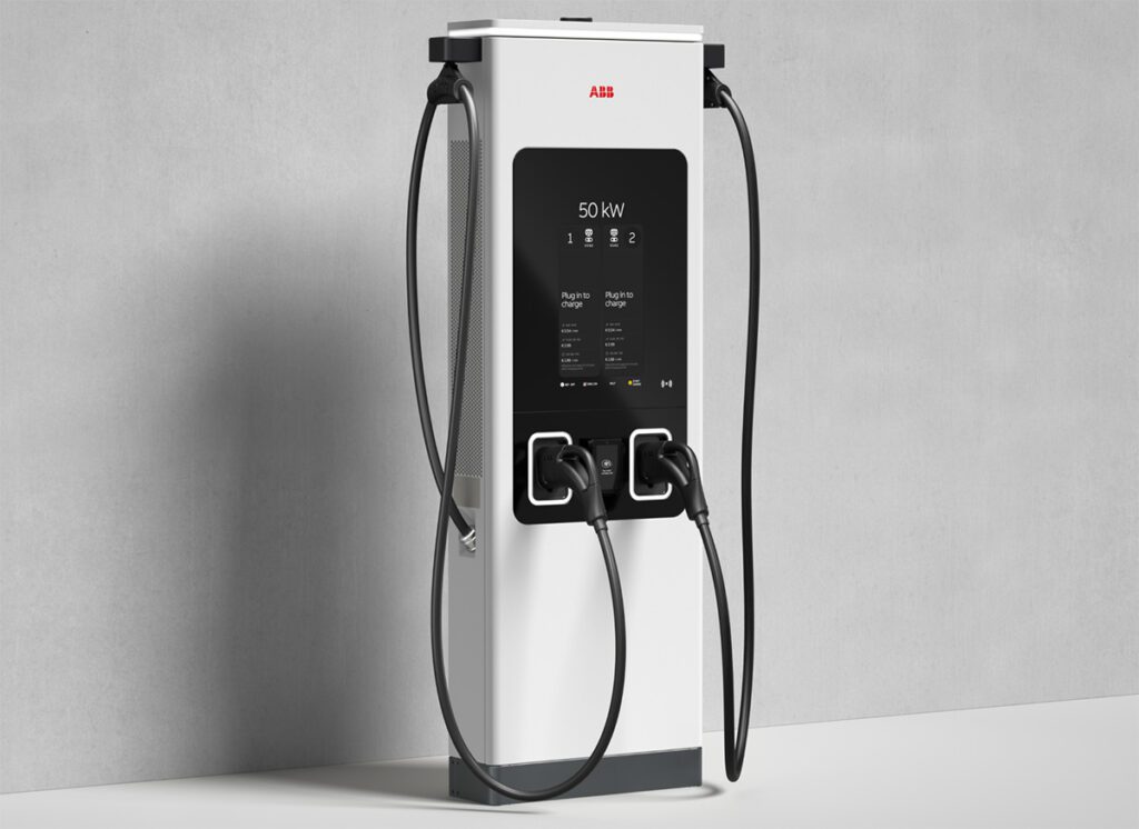
The role of a DC charging station is to convert power from the electrical grid (AC power) into DC power that can be directly fed into the vehicle’s battery system for charging of the battery. Since the conversion from AC to DC power is being done in the charging station, these units can provide higher levels of power (50 kW to 350 kW and beyond) to the vehicle compared to AC charging stations. This translates to a faster charging time (30 minutes or less).
Since DC charging stations are connected to the AC grid, fuses rated for AC protection are also instrumental for the connections to the grid. These AC fuses tend to be larger in nature since most DC chargers are installed on 3-phase utility supply (as opposed to single-phase supply connections for AC chargers). Additionally, earth/ground-fault protection is an important feature to incorporate into a DC charging station design, not only for the AC grid side but also for the DC output side. Most DC chargers are designed with electrical isolation from the AC grid, and thus the DC side must maintain isolation from everything else, including earth/ground. Earth/ground-fault relays for DC voltage systems are instrumental in detecting if an electrical fault has occurred in which the isolated DC side has a leakage path to earth/ground. These systems are often employed to minimize the risk of shock hazards to users.
Besides safety, efficiency in power conversion is a major challenge to overcome when designing DC charging stations. The effectiveness of a design is often measured by the amount of power a charger can deliver to a vehicle versus the amount of power it takes from the AC grid.
DC charging stations often employ several stages of AC/DC and DC/DC conversion to get the best level of performance while minimizing overall system size and cost. Efficiency in the power conversion process starts with power semiconductors. Power semiconductors are used to switch on and off the power source and to change the direction of power flow to create stages of alternating current that can be converted to differing levels of voltage or current.
This switching action in the power semiconductors leads to heating which is ultimately lost to the surrounding environment and contributes to the reduction of power available for delivery to the vehicle. New enhancements to diodes, insulated-gate bipolar transistors (IGBTs) and metal-oxide semiconductor field-effect transistors (MOSFETs) have allowed these devices to become ever more efficient. Additionally, the commercialization of wide band-gap technologies, such as silicon carbide, have helped newer generations of semiconductors minimize their switching losses to the lowest levels in the market today. With the constant evolution of these power semiconductor devices, there also comes an evolution to the types of drive circuits used to switch these devices on and off. Newer IGBT and MOSFET gate drivers are pushing the boundaries to provide faster switching and higher levels of isolation between the low-voltage drive circuits and the high-voltage power semiconductors.
Littelfuse’s application expertise has helped to design some of the most efficient next-generation power converters for EV charging stations.
For help designing the right level of safety, efficiency and reliability into your EV charging system, download your copy of our EV Charging Overview today.


