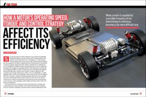
Efficiency is the name of the game in electric vehicle design and can affect vehicle range and energy costs. For a given device technology, there won’t be much efficiency advantage from one manufacturer versus another in apples-to-apples product comparison. However, there is another way to think of efficiency, and that is in terms of operational and functional efficiency. That is, looking beyond a device’s inherent efficiency and considering how and when it’s operated. This is where “smart” control solutions come into play and is particularly applicable to electrified auxiliaries, which rely on the control of independent electric motors to drive auxiliaries such as pumps and compressors rather than being mechanically driven by a combustion engine.
Smart solutions operate devices “on-demand,” which matches the output energy supplied with the actual energy demand based on the loading conditions or desired operation. This approach reduces energy consumption and audible noise by shutting the device off when not in operation or operating at a reduced or more efficient operating point.
This additionally reduces equipment wear and tear, thus extending operational lifetime or reducing maintenance requirements. Overall, smart solutions can impact day-to-day contributions to increased vehicle range, operator comfort, and total cost of ownership.
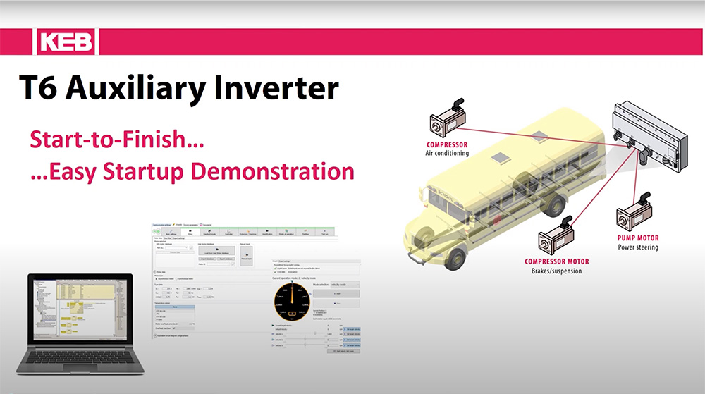
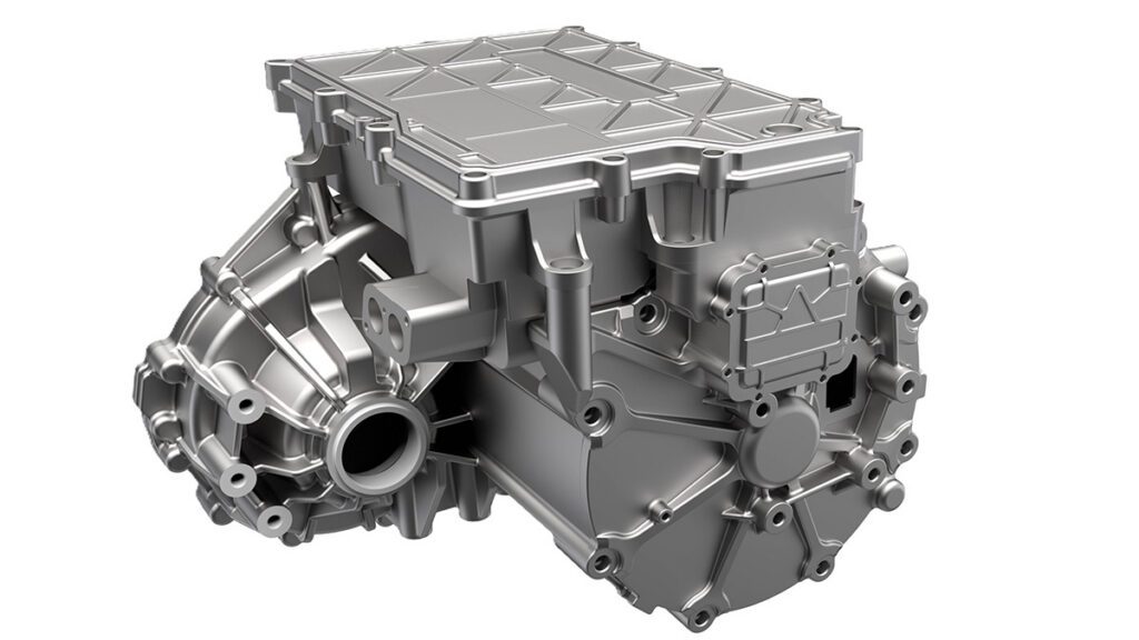
Energy-efficient and on-demand smart control solutions can be achieved in multiple ways. This article will focus on smart solution strategies for efficiently controlling auxiliaries such as pumps and compressors and some of the features of the KEB T6 Auxiliary Inverter system. The T6 is a high-voltage inverter system that supports up to 6 independent AC motor control outputs with modular power options (7.5kW, 15kW, or 30kW) for each output.

Advanced Motor Controls
Motor control methods determine how a motor is operated and rely on an inverter’s control algorithms to regulate the output power to the motor. Thus, different control methods can influence a motor’s operational efficiency. There are two primary control methods for AC motors, scalar, and vector control.
Scalar Control
Scalar control is also known as volts-per-hertz control and is an open-loop control type. Here, the inverter outputs a fixed voltage output for a given frequency corresponding to a command speed based on a Volts/Hertz curve from a motor’s rated operating point. Since the output voltage is determined by the speed command rather than the actual power requirements of the load, scalar control operation can be less efficient under partial loads. Scalar control also tends to have relatively poor performance since there is no speed or torque control and limited torque available at low speeds. Scalar control is very basic and only applies to asynchronous induction motors. It is outlined here to provide context to the benefits of vector control solutions.
Vector Control
A more advanced solution is vector control, also known as field-oriented control. This type of control is a closed loop that utilizes feedback from the motor. With vector control, there is independent control of both torque and speed. Additionally, the voltage output is optimized based on a vector calculation and operates more efficiently according to the actual load requirements.
Closed-loop systems also provide far better speed regulation and torque control, allowing for a high-performance response. This is particularly applicable when implementing on-demand auxiliary controls solutions that conserve energy by dynamically adjusting motor speed or switching systems off/on in response to an auxiliary device’s instantaneous or conditional power requirements.
Vector control can be used with asynchronous induction motors for increased operational efficiency and performance. In contrast, synchronous motors such as permanent magnet servo motors require closed-loop feedback of the rotor position to modulate the stator electromagnetic field angle. Encoder feedback and sensorless control algorithms have two types of methods for closing the loop.
Encoder vs. Sensorless Feedback
The traditional method used an encoder mounted on the motor shaft for speed and/or position feedback. The downsides are that the encoder and the cabling are additional system components that add cost, take up space, and are potential points of failure or susceptible to electrical interference.
Instead of encoder feedback, sensorless control algorithms utilize an observer motor model based on the motor characteristics and the actual measured motor current and voltage as feedback to close the loop. This eliminates the need for encoder hardware while providing comparable performance under most circumstances. Sensorless models have limitations at very low continuous operating speeds (<1% motor-rated speed) and would not be recommended for traction or holding applications but are otherwise ideally suited for use with pumps and compressors.
When considering sensorless control, it should be noted that only some manufacturers’ sensorless algorithms are equal. Although a comparison may be difficult to quantify, the essential characteristics include the speed control response and the torque control accuracy.
Furthermore, the simplicity of setup should be considered. KEB has been a leader in sensorless control development and performance for over 15 years, with extensive experience in pump and compressor applications across various power ranges and industries. Furthermore, the setup of sensorless control has been simplified with an automated motor learn procedure to characterize motors (only basic motor nameplate data is needed).

Embedded Control Solutions
Electrifying auxiliaries provide new opportunities for how these systems can be controlled. Beyond the motor control itself, smart solutions can also utilize innovative embedded control solutions.
Such solutions are often power on-demand control programs. These are used to control the motor based on the desired operation of the auxiliary and can also take into account several other factors within the vehicle to determine the optimal setpoint from an energy-efficiency or performance standpoint. This would be in contrast to a combustion engine-driven auxiliary, which would depend on engine speed. Instead, electrified auxiliaries can be controlled independently and intelligently precisely HOW and WHEN they are needed.
Power on-demand control programs can range from basic on/off control to dynamic performance and even more advanced algorithms which use sophisticated models of the auxiliary system and inputs from the vehicle to calculate the motor control setpoints.
As a use case example, a power steering pump would be an application that could readily benefit from smart power on-demand control solutions.
Traditionally, a power steering pump driven by an engine would constantly produce pressure and flow. The pressure is dissipated through relief valves as wasted energy when not fully utilized. An electrified auxiliary can instead use condition-based control programs to reduce energy consumption.
- A basic implementation would be to operate the pump motor at a reduced idle speed when the steering isn’t in-use, based on the steering angle sensor speed.
- A more advanced implementation may calculate baseline operating points for different speed ranges since the flow and pressure requirements vary drastically based on vehicle speed.
- Even more advanced solutions could use a hydraulic pressure sensor and (sensorless) motor speed feedback in PI control loops to more dynamically and precisely control the required motor speed and torque based on the actual demand requirements.

The T6 Auxiliary Inverter contains an embedded controller for easy integration of smart control programs. This allows system integration developers and auxiliary systems suppliers to implement their product know-how into custom, value-added functionality with ready-to-use smart software control solutions for their customers.


