Local air pollution, noise emissions, global CO2 reduction and public pressure are driving the need for zero emission transportation solutions in urban areas. Many OEMs are currently developing electrified heavy duty vehicles that maximize range and durability, while minimizing the total cost of ownership, system weight and vehicle packaging – electric axles (e-axles) offer one solution to meet these goals.
The implementation of e-axles into trucks and buses starts with finding the optimal architecture. A fully-integrated e-axle, with all electric drive (e-drive) components packaged together into the axle, allows for optimization of system weight and efficiency. However, integrating components into the axle can be challenging due to specific requirements based on (1) gross vehicle weight, (2) application, and (3) requested modularity for customer portfolio.
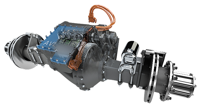
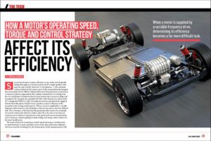
AVL Powertrain Engineering has developed a solution; the AVL e-axle system integrates all e-drive components into the central housing of the axle body, including (1) inverter, (2) electric machine (e-machine), (3) transmission, (4) cooling system, and (5) service brake. This high degree of integration reduces the number of interfaces to the vehicle and provides modularity with conventional drivelines.
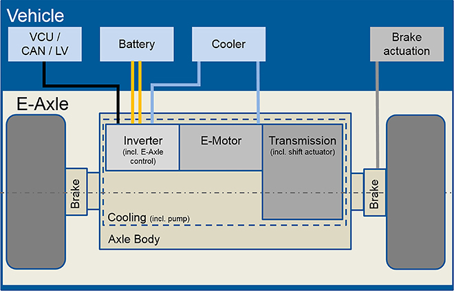
E-axle system with subsystems and vehicle interfaces provides OEMs with modularity for conventional drivelines.
The following is a use case from an AVL research and development project that examines different component specifications for designing an e-axle for a 16-ton delivery truck.
E-axle system specifications
Determining e-axle system specifications requires defining new parameters in addition to the given vehicle parameters, such as (1) tire dimension, (2) rolling resistance, and (3) gross vehicle weight. These parameters can be used to calculate the required e-machine power and the number of gears needed for the transmission. Meeting these parameters for a 16-ton delivery truck requires a continuous e-machine power of 148kW.
When defining major e-drive system specifications, the only required parameters are the e-machine power and number of gears in the transmission. This allows the e-machine speed range to be chosen freely and the transmission ratio to be adapted accordingly. These parameters can impact e-axle specifications in numerous ways, including (1) reducing e-machine power by lowering gradeability requirements, or (2) increasing e-machine power using a single speed transmission to minimize torque interruption.
The optimum configuration depends strongly on the boundary conditions and demonstrates the importance of setting the requirements according to the real needs of the specific application. The AVL e-axle is a well-balanced solution that achieves improved vehicle performance with a relatively low power e-machine.

Comparison of two e-axle specifications and the final solution selected by AVL.
Transmission configuration
Selecting the optimal transmission configuration for the 16-ton delivery truck required an assessment of different topologies, including (1) layshaft arrangements, (2) planetary drives, and (3) combinations of both. AVL found that the preferred topology was a layshaft arrangement using three (3) gear meshes for each gear, allowing a lightweight and compact variable arrangement with high efficiency.
The transmission of the e-axle is designed to reach highest efficiency. The required ratio is reached with only three (3) meshes of helical gears. With this set-up, the bevel-gear-set of a typical conventional driveline can be avoided.
The interface between electric motor (e-motor) and transmission is designed in a way that no axial or radial loads are transferred between e-motor and transmission, creating better noise, vibration and harshness (NVH) behavior.
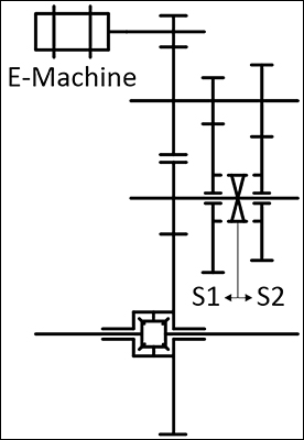
Diagram of transmission topology the layshaft arrangement with the three (3) gear meshes at each gear.
E-motor technology
The selection of e-machine technology is driven by two parameters: (1) packaging requirements, and (2) product cost. Packaging requires a technology with high power density. Target cost constraints demand the most economical solution for the combination of e-machine and power electronics.
Permanent magnet synchronous (PMSM) e-machines are proven as the mainstream technology due to their outstanding power density, cost advantages, robustness, and safety considerations. Other e-machine technologies are typically used more for niche applications.
For this specific truck e-axle application, AVL opted for the PMSM technology due to the demanding packaging requirements, as well as the high efficiency at lower speed levels (e.g. urban driving cycles).
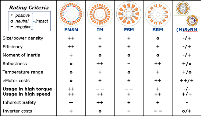
Overview of strengths and weaknesses of different e-machine technology.
Inverter
Similar to the e-machine, the two major design criteria for inverters are (1) packaging, and (2) unit cost. Unit cost of the inverter is driven mainly by the processed current, which also influences the cost of switches, capacitors, and busbars.
It’s possible to reduce current per switch by increasing the voltage level or by increasing the number of phases. The most obvious choice to reduce current per switch is to increase the system voltage; at any given current, when the voltage is doubled, the power also doubles. When increasing the voltage level is not an option, an alternative is to increase the number of phases of the e-drive system from 3 to 6 (or even 9); this approach allows phase currents to be reduced by half or one third.
After considering these trade-offs, AVL decided on a 3-phase solution for the inverter. At the 800V level, the required continuous power can be supported with standard insulated-gate biopolar transistor (IGBTs), resulting in a cost-efficient solution. AVL’s long history with 800V inverter technology and its modular sub-component design allows the company to develop reliable and cost efficient power electronics for this e-axle.
For this 16-ton delivery truck, 800Hz maximum output frequency was selected to reduce switching losses, limiting the maximum speed to 16,000rpm at three (3) pole pairs.
E-axle cooling system
The main challenge for selecting a cooling system is the varying temperature levels preferred by the components. With the AVL e-motor system, oil is used as a coolant. The system is split into two circuits – one circuit is used for the transmission lubrication, while the second circuit cools the inverter and e-motor. By separating the transmission lubrication circuit, the temperature level of the e-drive cooling circuit can be kept at a suitably low limit.
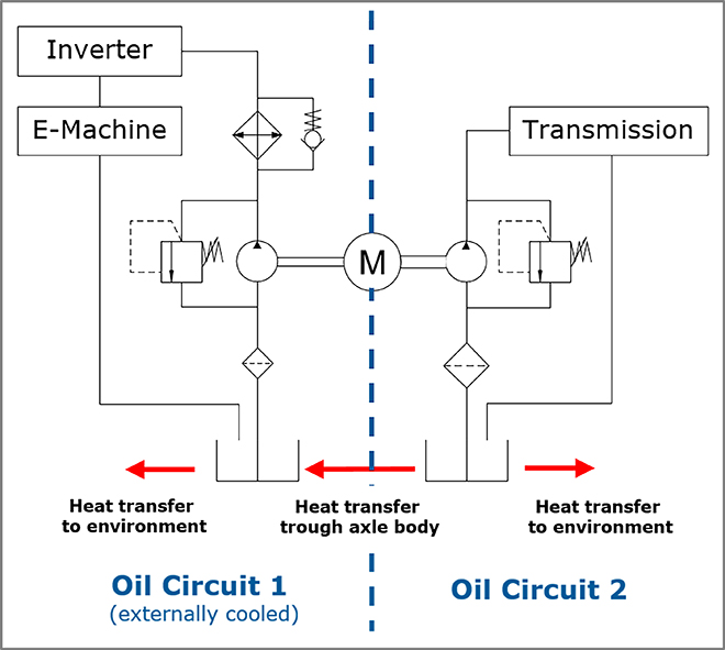
Schematics of preferred e-axle cooling system showing that each component is kept at a suitable temperature through separate transmission lubrication circuits.
E-axle packaging
Since e-axles require more installation space than conventional axles, some vehicles require modifications to create space around the axle. These modifications include (1) repositioning the suspension system, (2) using rectangular brake actuators located directly on the e-axle, and (3) shortening the transmission to allow for a longer, smaller diameter e-machine to be integrated.
The axle body was designed to have the power electronics module directly mounted onto it, avoiding separate housing. The electro-mechanical gear shift actuator, lubrication pump, and transmission output speed sensor are also located within the integrated inverter housing – allowing all electrical components, including complete wiring, to be protected from environmental impacts.
Added value of AVL’s e-axle
AVL’s e-axle can be packaged for use in conventional HD vehicles without major component modifications, and achieves power requirements with cost effective components. The highly integrated e-axle contains the complete e-drive, ensuring low system cost and weight, as well as maximizing efficiency. Using this configuration, overall system complexity is reduced due to limited vehicle interfaces. OEMs will find that the existing e-axle concept’s high performance and reduced packaging ensure flexibility, system reliability, and low production costs.
Contact AVL today to find out more about its electrified solutions.


