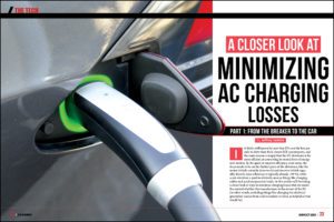
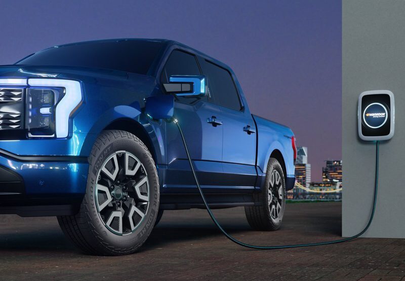
The adoption of electric and hybrid electric vehicles depends on a network of charging stations. Consumers don’t want to run out of juice in a place where they cannot recharge their vehicles.
Adoption also depends on reductions in charging time, the goal being to get EV charging time on par with a conventional fill-up. This in turn depends on high-power charging stations having more than 50 kW of charging power which are relatively more expensive.
Given the importance of charging stations, the level of power involved, and the investment required, it is essential that EV charging system designers plan for safety, efficiency, and reliability.
Safety. Consumer safety is paramount. Until the advent of DC charging stations, the general public has not had access to power higher than the 120 V they see at home in the wall socket. Newer EV chargers deliver 400 to 1,000 V DC. EV chargers must minimize the threat of electrical shock and other hazards.
Efficiency. Power conversion is crucial for DC fast charging systems. Minimizing losses in power conversion ensure the maximum amount of power delivered for charging the vehicle’s battery and reduces heat buildup.
Reliability. Once installed, the EV charging equipment must operate dependably for 10 or more years, even in the harshest outdoor conditions, to ensure an acceptable return on investment.
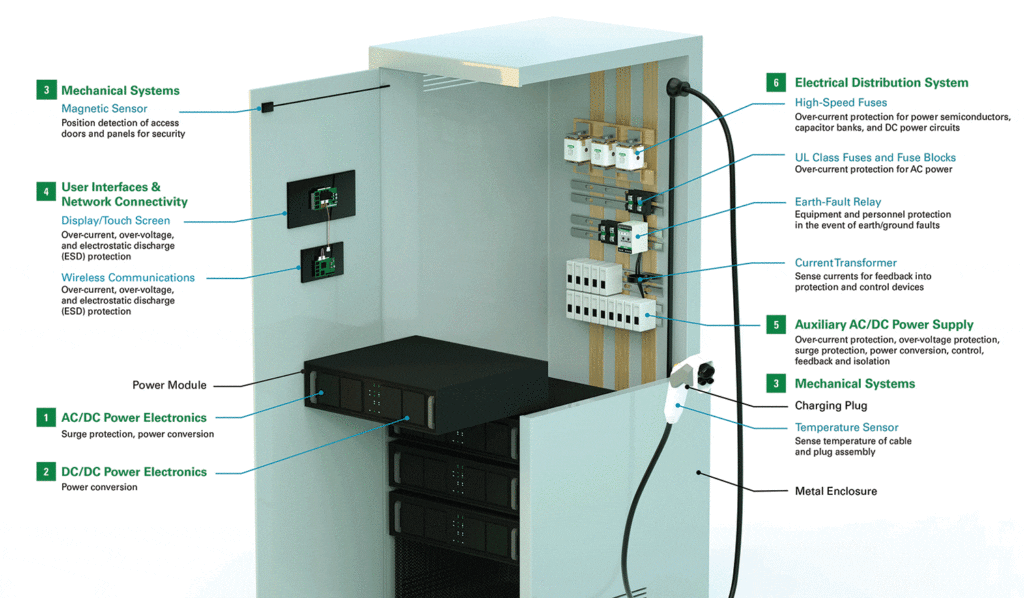
Safety
The two biggest safety threats in an EV charging station are electrical shock and overcurrent. Electrical shock is usually the result of a ground fault.
Electrical shock
A ground fault is an unintended contact between an energized conductor and ground or the equipment frame. Insulation breakdown is the typical culprit. Also, dust and moisture can cause unintended pathways for electricity. Wet and dusty environments, such as those found around outdoor equipment, require diligence in design.
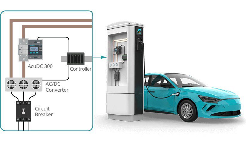
AC ground-fault protection is needed on the input side of the design to protect components from damaging faults, and to protect consumers from electric shock should the equipment frame or housing become energized. A ground-fault protection device uses a current transformer on the phase conductors to ensure that all current coming from the source returns on those same conductors, or it reads the current in the connection between the transformer neutral and ground. A ground fault anywhere in the system will return current through this path.
Similarly, ground-fault protection is required at the output side, so that when a consumer picks up a nozzle capable of 1,000 V, the handle or the frame is not energized. A DC ground-fault monitor is installed on the output side to detect any earth leakage and shut off power immediately. As the output side is not grounded, the ground-fault monitor depends on a ground-reference module between the two buses to establish a neutral point, which is used as a reference to detect low-level ground faults.
Overcurrent
By their nature, vehicle charging stations are connected to a power supply that has high available fault current. Electrical faults, including those that start ground faults, can draw high current that can be very destructive, damaging components, twisting bus bars, starting fires, and even cause an arc-flash incident—a kind of explosion that could injure or kill anyone standing nearby.
Select fuses based on their interrupting capacity, their rating based on normal operating current, and their time-current curve characteristics. “Current limiting fuses” operate quickly in the event of a high-value overcurrent, which limits peak let-through current.
Unless interrupted quickly, even moderate overcurrents can overheat system components, damaging insulation and conductors. However, the worst damage will be to the many electronic components, many of which are susceptible to even low-value overcurrents.
Efficiency
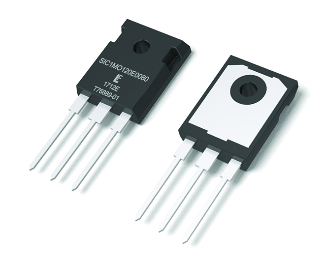
Power semiconductor devices convert AC power into the DC power needed to recharge vehicle batteries. To match the level of charge to what the vehicle battery needs, the power semiconductor device controls the charge through switching, a process that naturally incurs power losses in the form of heat. In an EV charging application, the heat can create engineering challenges.
That’s why advanced technology devices based on SiC and GaN technology are utilized in power conversion; compared to silicon devices they provide ultra-fast switching for lower power losses.
SiC MOSFET devices are now available that blend high operating voltages and fast switching speeds, a combination typically not available with traditional power transistors. To be useful in automotive charging applications, they must operate at high junction temperatures and feature low gate resistance, low gate charge, low output capacitance and ultra-low on-resistance. Designers prefer devices that offer high power density and reduce the size and weight of filter components, which reduces cost and space requirements.

Reliability
Unlike consumer devices like laptops that are engineered for a lifetime of three to five years, DC charging stations are expensive, so buyers need them to last for 10 years or more, in order to get a return on their investment. The value of semiconductor content alone ranges from $350 in an AC charger to more than $3,500 in a 350 kW charging system. Proper circuit protection will keep that investment working reliably for a longer amount of time.
Semiconductor devices are sensitive to electrical threats and must be protected from overcurrent by fuses. These devices are typically fabricated from silicon or silicon carbide and have low thermal withstand capacity.
Conventional fuses are sufficient to protect most of these, but specialized high-speed DC fuses are needed to protect power semiconductor devices such as MOSFETs, IGBTs, diodes, and thyristors used in power converters (inverters, rectifiers, etc.) Such fuses are engineered with a specific time-current characteristic so that they operate very quickly compared to traditional AC input fuses.
Another threat to sensitive semiconductor devices is overvoltage. If an EV charger is located near an industrial facility with large motors, the switching on and off of those motors can produce voltage surges in the power supply. Also, if there is a lightning strike near the charging station, the electromagnetic energy may induce a voltage surge on the power lines in the neighborhood that could propagate into the charger via the AC power input lines. Overvoltage protection devices must be used to absorb that energy, preventing it from damaging the sensitive electronics that make the charger work.
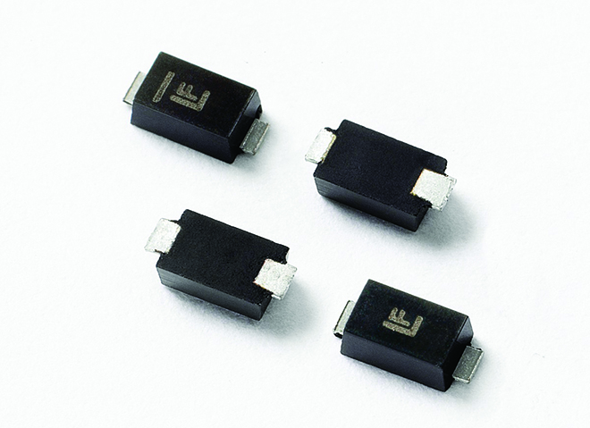
Circuit protection devices are made with different technologies. While many types of devices may work, it is better to select a device having the ideal technology for that application. In a DC charging system, a high-power Transient Voltage Suppressor (TVS) diode or metal oxide varistor (MOV) is usually the best type of suppression device. Other types of protectors—such as protection thyristors, gas discharge tubes, and multi-layered varistors (MLV) or combinations of suppression devices — are often specified.
When it is used to protect sensitive circuits, the length of time a transient suppressor requires to begin functioning is extremely important. If the suppressor is slow-acting and a fast-rising transient appears on the system, then the voltage across the protected load can rise to a damaging level before suppression kicks in.
Reliability, efficiency, and safety are achievable in EV charging station designs. Littelfuse offers a white paper on this topic that includes block diagrams and specific device recommendations.
Download the guide, Supercharged Solutions for EV Charging Stations.

