
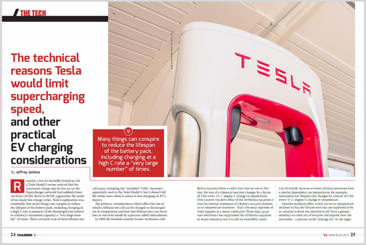
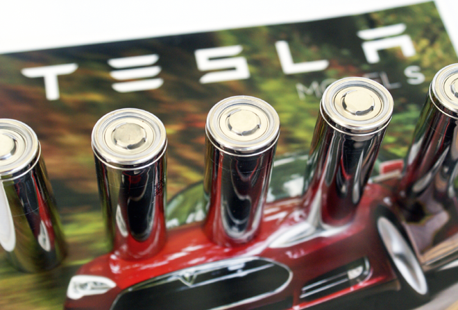
Recently, a bit of a kerfuffle kicked up when a Tesla Model S owner noticed that the maximum charge rate for his car on the Supercharger network had suddenly been cut from 120 kW down to 90 kW, apparently the result of too many fast charge cycles. Tesla’s explanation was, essentially, that many things can conspire to reduce the lifespan of the battery pack, including charging at a high C rate (a measure of the discharged rate relative to a battery’s maximum capacity) a “very large number” of times. That’s certainly true of most lithium-ion cell types, including the “modified” NMC chemistry apparently used in the Tesla Model S, but it doesn’t tell the whole story when it comes to fast charging an EV’s battery.
The primary considerations which affect the rate at which a lithium-ion cell can be charged or discharged are its temperature and how fast lithium ions can move into or out of its anode by a process called intercalation.
In 1889 the Swedish scientist Svante Arrhenius codified in equation form a useful rule that we use to this day: the rate of a chemical reaction changes by a factor of 2 for every 10-11 degree C change in temperature. One counter-intuitive effect of the Arrhenius equation is that the internal resistance of a battery actually declines as its temperature increases – that’s the exact opposite of what happens in a metal conductor. These days, quantum mechanics has supplanted the Arrhenius equation in many instances, but it is still an incredibly useful rule of thumb, because so many physical processes have a similar dependency on temperature: for example, semiconductor lifespan also changes by a factor of 2 for every 10-11 degree C change in temperature.
Another insidious effect which occurs as temperature declines is that the lithium ions that are supposed to be in solution to form the electrolyte will have a greater tendency to come out of solution and deposit onto the electrodes – a process called “plating out” in the argot. This is about the worst thing that can happen to a lithium-ion cell, because it permanently decreases capacity – lithium is what stores the energy in a the cell, after all – and can eventually cause internal shorts, usually with exciting (read: disastrous) results.
The tendency for lithium to plate out is also more pronounced at higher charge/discharge rates, so one potential solution is to limit current at low temperatures (what is considered “low” depends on the composition of the electrolyte and the cell construction) to encourage self-heating from the higher internal resistance, but not inhibit charging completely until the battery is in danger of actually freezing. While this might sound good on paper, it can be a royal pain to implement in practice because there must be lots of temperature sensors sprinkled throughout the pack to have a good chance of identifying the coldest (and hottest) cells. If you are the manufacturer of both the vehicle and the fast charger, then this is not so much of problem, as you can put as many temperature sensors inside the pack as necessary and make sure your fast charger acts upon that information. It is when the driver of the vehicle wants to use a third-party fast charger that the headaches begin – can the charger even read the temperature sensor data, and, if so, will it act upon that data in an appropriate fashion?
The next factors to consider center around the charger itself, including how it operates and the wiring that connects it to a source of power as well as to the vehicle. A dodgy connection in the charging circuit at 1 A or even 10 A of current might not ever be noticed, but cram 100 A to 250 A through it and things will start lighting up like the Fourth of July. In 2016, a Tesla Model S in Norway caught fire within minutes of being plugged into a Supercharger, and the most likely cause was determined to be a bad connection inside the car. Interestingly, the Supercharger did eventually detect a problem and shut off, but whether that problem was an inability to deliver the expected amount of current, or from monitoring the voltage drop along the entire charging circuit, is unknown.

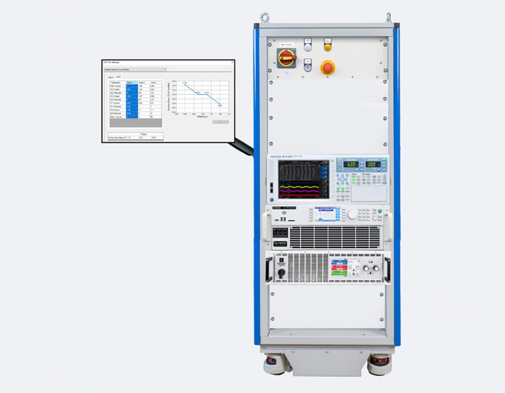
The surest way to protect against this kind of problem – which, by the way, is a very common cause of failure in high-power electronics – is to measure the voltage drop at various points along the entire current pathway from inside the charger to the final connections at the battery pack (and even between cells, ideally). If the voltage drop between two points is too high for the amount of current flowing, then there is too high a resistance present. For example, if the voltage before the charger plug is 400 V while the voltage after the charge port inlet is 399.5 V, then the voltage drop across the charger connection is 0.5 V, and if the charging current is 100 A, then the resistance is 0.5 V / 100 A = 5 mΩ, or 5 thousandths of an Ohm. That doesn’t sound like much, but the power lost as heat across this resistance would be 100 A * 0.5 V = 50 W. However, detecting the voltage drops between various points of the charger-battery circuit is yet another example of an idea which sounds good on paper but which can be difficult to implement in the real world: after all, measuring a 0.5 V change out of 400 V requires better than 0.06% accuracy. One common solution is to make true differential measurement between points, and, ideally, float or isolate the measurement circuit from the charger, battery pack and even earth ground.
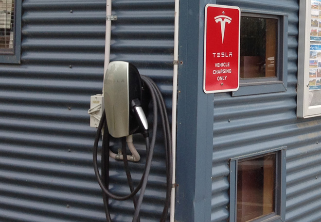
For similar reasons, the voltage drop along the AC mains wiring that supplies the charger needs to be monitored as well. In 2013 a Tesla owner’s garage caught fire while the vehicle was charging via the onboard Level 2 charger, and while a final cause was not identified in the legal sense of the word, there was plenty of circumstantial evidence pointing to the AC wiring or the outlet overheating from…you guessed it, excessive voltage drop. As a consequence of that incident, Tesla modified the charger firmware to shut down if the AC mains voltage drops too much with respect to the amount of current being demanded. This is a much more variable situation however, because the voltage drop could be the result of relatively benign causes, such as the distribution transformer being heavily loaded (usually one transformer supplies several houses) or the wiring run between the load panel and charger outlet being a bit longer than is ideal (in this case, while a lot of wattage might be wasted in an absolute sense, the heat generated is spread out over a long run of cable, so the temperature rise is barely noticeable).
Then there is the charger itself. The primary consideration for the charger is how much power is available to supply it; if all you have is the standard residential 120/240 V electrical service in North America, then be aware that electric utilities often assume an average demand of 10 kVA per house and size their distribution transformers accordingly. In other words, that 200 A load center installed in many new homes can’t really be used to supply 200 A continuously, nor even the 160 A supposedly possible if one were to follow the NEC rule that no circuit shall be loaded to more than 80% of its wiring ampacity. Thus, to accommodate a charger rated for 10 kW or more (assuming it has power factor correction) you will either need industrial 3-phase service or a solar panel array and a battery bank; with just a common 240 V/50 A “range” outlet in the garage you will be limited to 10 kW (again, assuming a unity power factor). And while few utilities will upgrade a distribution transformer just because you asked them to, they will upgrade it if it fails from chronic overloading. Of course, you’ll probably have to suffer without power for a day or two before they send a truck out, so plan accordingly!
The other consideration with the charger is whether to go with a modular design – that is, many smaller chargers operating in parallel – or a single high-power design.
The modular approach can offer some level of redundancy, and it is relatively easy to scale up output power by adding more modules. However, it will generally cost more for a given power output, and at some point adding more modules to get more power turns absurd. So an intelligent choice of power for each module is required; after all, you don’t really want to make a 60 kW CHAdeMO charger out of 1 kW modules. It’s worth noting that Nissan and Tesla both take the modular approach: Nissan uses two 3.3 kW chargers for its on-board 6.6 kW charger in the LEAF, and Tesla uses twelve of the same 10 kW Model S chargers in each 120 kW Supercharger.
Finally, at the risk of pointing out the obvious, you either need a high-power AC input charger on board or a DC inlet such as the SAE J1772 Combo Charging System (CCS), CHAdeMO or Tesla’s proprietary connector to safely charge an EV; let’s leave the Anderson connectors to the forklifts and pallet jacks of the world!
Read more EV Tech Explained articles.
This article originally appeared in Charged Issue 31 – May/June 2017 – Subscribe now.