


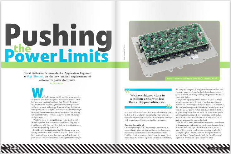
With each passing model year, the requirements demanded of automotive power electronics increase. Market forces are pushing Insulated Gate Bipolar Transistor (IGBT) modules towards lighter, smaller, more powerful and more reliable technology. These switching devices are what power an EV or hybrid inverter, and with increasingly stringent emissions requirements, automakers are looking for more innovative solutions to power their next electrified products.
“We have yet to see the golden age of the electric car,” Nitesh Satheesh, Semiconductor Application Engineer at Fuji Electric, told Charged. “But that day is not too far away and we are preparing to serve it.”

Fuji Electric, first established in 1923, began mass-producing automotive IGBT modules in 2005. “Since then we have shipped close to a million units, with less than a 10 ppm failure rate,” boasts Satheesh. He says that the company continually strives to achieve a zero-defect future and, to that end, is constantly implementing new combinations of design and process-control techniques, combined with screening and focused reliability engineering.

One size doesn’t fit all
Choosing the right IGBT for the right application is no small task – there are many different configurations from many different semiconductor manufacturers. Fuji Electric’s first mass-produced module was a 2-in-1 Buck-Boost for a major Japanese automaker. Since then, the company has gone through numerous iterations, and currently has several standard offerings of automotive-grade modules, including 6-in-1 packages rated for 650 V, 400 A and 600 A.
A system’s topology is what dictates the size and functional requirements of the power module. One-motor systems for hybrids typically have a parallel connection of the combustion engine and the electric motor/generator. That means the power system can either be in motoring or generating mode, but not both. For one-motor system implementation, Satheesh recommends a combination Buck-Boost, 6-in-1 module (a total of 8 switches) to effectively produce the required output.
On the other hand, a two-motor system in a vehicle can be in generating and motoring modes simultaneously. In that case, Satheesh says a Buck-Boost, 6-in-1, 6-in-1 (a total of 14 switches) produces the required results. For example, Figure 1 shows a custom first-generation 14-in-1 Intelligent Power Module built for Honda’s Accord Hybrid, in production since December 2012.
The next gen
Fuji Electric is actively working with partners to optimize new solutions, and will soon announce its next generation of automotive power modules for the general market. The company has taken a two-pronged approach to quickly adapt to market requirements, with a portfolio of “standard” Automotive Power Modules built to automotive standards of reliability, and the “custom” Power Modules/IPMs.
Lightweight
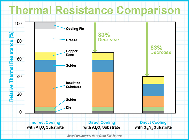
Design engineers always face trade-offs between cost and performance, and creating lightweight cooling solutions for IGBTs is a classic example, with aluminum competing to be a low-cost and lighter alternative to copper.

Satheesh told us that the challenge Fuji Electric faced was to develop an aluminum cooling solution with performance equal to, if not greater than, that of its copper cooling system. “By implementing a new structural design of the cooling fins, the company was able to achieve a dramatic reduction in thermal resistance of its aluminum system,” explained Satheesh. This meant a 70% reduction in weight moving from the first-generation copper cooling to the first-generation aluminum cooling setup.
High power density and high efficiency
Ask anybody about his or her thoughts on EVs, and the conversation will quickly lead to the topic of range. Fortunately for the plug-in vehicle industry, advances in battery technology and more efficient power conversion are leading to great leaps in all-electric capabilities.
In power electronics, advancements have been achieved by improving IGBT and Free Wheeling Diode (FWD) design. “With each passing Fuji Electric chip generation, a reduction in IGBT saturation voltage and turn-off loss has been realized,” said Satheesh. “We have also optimized the gate structure with the introduction of the Trench Gate in our fifth-generation IGBTs. Reduced conduction and switching losses were achieved with the thinner wafer – a result of the field stop optimization – and lifetime control, respectively.”
These improvements in chip technology effectively increase the module’s current density. “This may raise an important concern in the minds of the reader, that of thermal conduction,” Satheesh noted. “Logically, as the chip area reduces, the thermal resistance should increase, and that is true. However, this effect is nullified using advanced innovative cooling devices. Tight lifetime control in the diode has also resulted in significant reduction in the dynamic loss of the FWD, and the thinner wafer has reduced conduction losses.”
High-reliability packaging
A power module, like any other component, is expected to last the lifetime of a vehicle. However, the lifetime of the module varies greatly with the drive profile. With IGBTs, there is a big trade-off between required reliability and cost. Many different causes of failure can arise in a power module, mainly due to the mismatch in the coefficient of thermal expansion for the materials used in packaging. Repeated thermal cycling stresses the materials, eventually causing them to fail, and manufacturers are expected to have a detailed idea of exactly when these failures will begin to occur. “It helps to have a model to accurately predict this time to failure,” said Satheesh. “Fuji Electric provides lifetime curves based on a combination of experimental results and extensive simulations.”
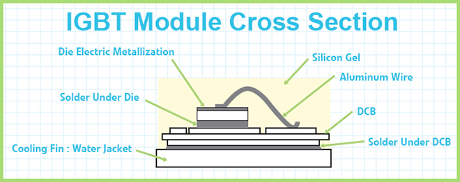
Some of the common causes of failure, and Fuji’s new solutions, include:
Aluminum bond wire lift-off
This is the most common failure mode at lower differences in junction temperature (Δ Tj). Failure occurs due to grain growth, which weakens the bond between the chip and the aluminum wire. Satheesh says that Fuji Electric addressed this problem by changing the re-crystallization temperature of the wire, limiting the growth of grains.
Solder layer cracking
In the middle Δ Tj range, the common failure mode is cracking of the solder layer. Fuji Electric says it solved this issue by developing a tin-antimony chemistry, along with other elements, to suppress growth of cracks.
Electrode metallization
This failure mechanism usually occurs in the higher Δ Tj ranges. To tackle the problem, Fuji Electric began passivating the Al-Si layer with a Ni layer.
The trick in IGBT design is not to oversize – or over-engineer – any of these components, but to build modules that will last exactly the right amount of time for any given application. The automotive industry is an unforgiving one, and achieving a low-cost, high-reliability solution is no longer a goal – it’s a requirement.
This article originally appeared in Charged Issue 16 –November/December 2014
![]()