Digatron Firing Circuits’ new stop-start testing rig examines the limitations of lead-acid batteries and the inadequacy of traditional static tests.
As the battery in a stop-start system ages, the fuel efficiency advantages are curtailed. It’s a real problem found in some first-generation systems, and has led many to question the methodology used in urban-efficiency tests. Ralf Hecke, of Digatron Firing Circuits, says it highlights issues with stop-start battery testing practices. Hecke develops test and load simulation systems at Digatron, and has been working on stop-start technology for a few years. Talking to Charged, he recalled his early work at a major automaker where a computer simulation was used to predict the charging needs of a stop-start battery. “The real world looked totally different,” he told us.
 At Digatron, Hecke set out to develop a proper test system to simulate all the loads and charges seen in real-world stop-start applications.
There have been tests developed by some organizations – like the Japanese automotive and battery industry, for example – but Hecke believes their models are too simple and have been adapted to existing test equipment rather than focused on the actual cycles seen in the field. “We wanted to have the exact behavior that we saw on the road in the laboratory environment,” he said.
In stop-start applications, the battery sees many different charging and discharging scenarios that a battery in a conventional vehicle would not. To properly test a battery, battery monitoring system (BMS), and energy management algorithm, Hecke insists it is critical to simulate all of the real-world phases. While the operation of each stop-start system differs depending on its design, some of the basic charging and discharging phases include:
The Cranking Phase
In a stop-start system the cranking phase is generally the same as in conventional vehicles, although it obviously happens more often – somewhere around 10 times more often, depending on driving habits. Here the battery experiences high-power discharge for a brief period, and the actual amount of energy you take out is minimal.
 Zero Current Phase
The basic idea is that the less energy shuttled through the battery the better, because it will always involve some losses from the electrochemical processes and unnecessary cycling of the battery. Every automaker employs different specific strategies, but in general the system tries to maintain the battery at an 80 percent state of charge (SOC), with 20 percent reserved for recuperation.
Instead of using a fixed voltage set point regulator, the voltage can be varied. So, while driving with an 80 percent SOC, the management system will adjust the voltage set point of the alternator in such a way that there is no energy removed from or put into the battery. If all of the electronic loads in the vehicle – the radio, headlights, etc. – require 40 A, then the alternator set point is adjusted to produce that current.
Recuperation Phase
Energy recuperation occurs during deceleration. In one common system, for example, the kinetic energy of the vehicle will continue to turn the engine with the clutch still engaged, and torque the alternator, although no fuel is consumed. During this phase the voltage set point of the alternator is increased as high as the PowerNet will allow, typically around 15 V, and current flows into the battery.
In the best-case scenario the battery would accept as much energy as the alternator could deliver. If the alternator output is 150 A, and 40 A is the actual load of the vehicle, the battery would be charged at 110 A. But the rate that batteries can accept charge varies greatly depending on a number of factors, including chemistry, temperature, and age. So, the amount of recuperated energy is limited either by the alternator’s output or the battery’s charge acceptance.
Unloaded Alternator Phase
After a recuperation phase, when the battery is above 80 percent SOC during normal driving conditions, the alternator voltage set point can be lowered below the voltage of the battery (or the alternator can be mechanically decoupled altogether). In this case the battery supplies all of the energy for the vehicle’s load, and the alternator is fully unloaded, relieving drag from the drivetrain, which allows faster acceleration and better fuel efficiency.
This phase can also be scheduled for points at which the combustion engine sees the worst operating conditions – high fuel consumption but low power output. The best time to release the captured energy can be pinpointed based on the vehicle’s fuel maps.
Fuel-Consuming Charging Phase
Like the cranking phase, this phase is relatively self-explanatory, and generally the same as in conventional vehicles. When the battery is below the desired 80 percent SOC, the alternator will charge the battery via the torque created while the engine is consuming fuel.
Engine Off Phase
When the vehicle comes to a stop – at a traffic light, for example – the combustion engine turns off, and the battery now carries all the vehicle’s electrical load (headlights, seat heaters, radio, control modules, etc.). This is the major discharge phase of the battery, and it is critical that the energy management system preserves enough energy for a safe restart.
If the vehicle comes to a stop and the battery has a SOC below a minimum desired value, the energy management system will skip this step and continue to operate in the fuel-consuming charging phase.
After Run Phase
This phase is the period of time after the vehicle is parked and keyed off before it enters the sleep phase – generally around 10 to 20 minutes, depending on the vehicle. Here the ECUs and the internal bus traffic of the electronics are still active, with a fair amount of current flowing.
The Sleep Phase
In this phase the vehicle could be considered dormant, with most of the systems powered down. The current flow in sleep mode is usually around 10 to 20 mA.
The Wake Up Phase
Typically, when a vehicle is unlocked, it will exit sleep mode and enter the wake up phase. This is similar to the after run phase, in which the ECUs power up and the electronics begin internal communications.
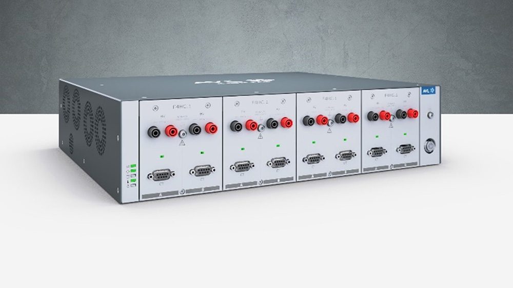
To accurately simulate all of the possible phases of a stop-start system, Hecke developed a “hardware in the loop” (HIL) system. The laboratory test setup included two power circuits: one to simulate the sink, with a high current capacity to mimic the cranking phase, and another to simulate the alternator. This enabled testing of the zero current phase with both circuits operating at the same time. To test different real-world scenarios, eight drive cycles were simulated with various combinations of probable operating phases and recuperation events.
Hecke’s laboratory work detailed the importance of simulating the sleep phase of the vehicle, which many other testing methods have ignored. Within Digatron’s simulated drive cycles are daily 12-hour periods of a parked vehicle, as well as a two-week parked period every sixth week.

Hecke found situations in which, after a two-week parked period, the relatively small load of the sleep phase would drain a 12 V lead-acid battery’s SOC below the minimum that’s required to enable the stop-start functionality. In this case, the vehicle would operate like a conventional car, burning fuel while idling to charge the battery. The period of time it takes for the system to return to full stop-start functionality is directly related to the charge acceptance of the battery. And the charge acceptance is a key variable that’s clearly affected by the battery’s age, again highlighting the importance of accurate life predictions.
The test was originally developed to examine the limitations of using 12 V lead-acid batteries in stop-start applications – and the inadequacy of traditional static tests – but the same setup is suitable to test other battery chemistries, energy storage devices, or combinations of them. Digatron plans to use its new testing system to more accurately compare and contrast the different energy storage options available to stop-start system designers. Through a precise simulation of the interactions between the battery, BMS, and energy management system, Hecke believes the advantages of using advanced batteries and capacitors will be made clearer.

“People are trying to find an energy storage device that always accepts a lot of energy. Ultracapacitors can do it, and so can lithium-ion batteries. There have also been many developments in advanced AGM and improved flooded batteries for stop-start applications. Some combine the use of lithium-ion batteries or ultracapacitors with lead-acid, so that during the recuperation phase they can always take a lot of charge,” Hecke explains. “The charge acceptance of a traditional lead-acid battery is good for only about three months in the field, then it gets to a level where you don’t have a lot of recuperation benefits. These advanced storage devices are very well suited, because they have a very predictable high charge acceptance over time.”
The life expectancy of a stop-start battery depends on the region, but ideally, it is designed to match the life expectancy of a typical vehicle’s battery. “Here in Germany, we average 4-5 years for a battery,” says Hecke.

