
Battery technology is an ever-changing, ever-improving field that has gained a great deal of momentum in recent years. With improved energy density, power density, and cost comes a huge variety of new and exciting applications in a wide range of industries. The future looks bright. But the future won’t be enabled solely by advances in chemistry and manufacturing processes.
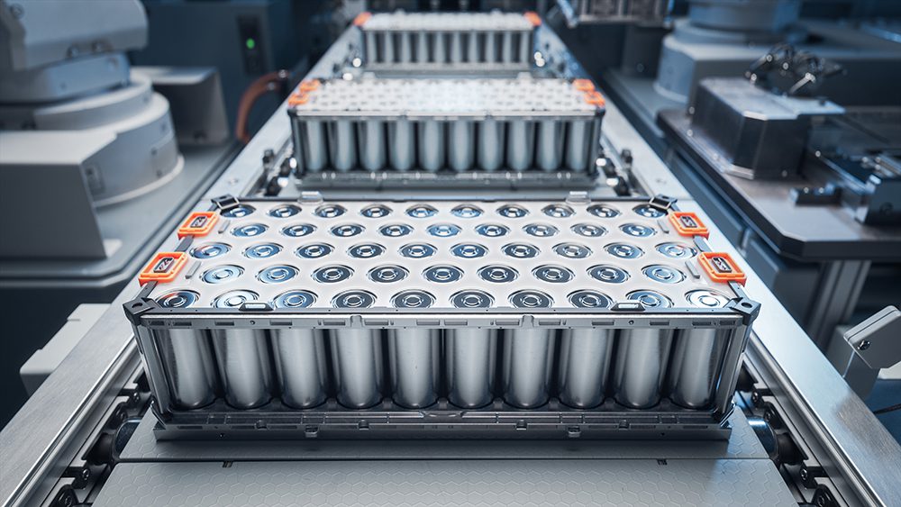
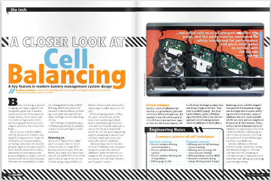
To get the full benefit out of modern battery technology, individual cells must be grouped together into packs, and the packs must be monitored for safety, maintained for performance, and given intelligence to connect with the outside world. All of these functions fall under the responsibility of a Battery Management System, or BMS. Building a BMS that unlocks the potential of modern battery technology is no small task, and there are many challenges to overcome along the way.
The challenge of implementing a cell balancing solution, for example, is multi-faceted and highly system-dependent.

Balancing act
The level of “balance” (or “imbalance”) of a pack refers to the difference in state of charge (SOC) between cells in the pack. With any battery pack made up of more than one cell, the usable SOC of the whole pack is only as high as the cell with the least energy. A good BMS will balance cells accurately and quickly, improving the usable capacity of the pack.
When designing a multi-cell battery pack, two questions quickly arise when considering the BMS: Does it need balancing? And if so, what method should be employed to ensure that the pack remains balanced? As with any good engineering analysis, attempting to answer these will raise complicated issues that need to be carefully examined.
There are many factors that affect the level of imbalance one can expect in a given system. The causes of imbalance can be divided into two categories. For the purposes of this discussion, we’ll call them “intrinsic” and “dynamic” sources.
Intrinsic imbalance
Intrinsic causes of imbalance are inherent to a given battery pack and will always behave the same way. For example, if one cell within a pack of 100 cells has a 5 percent lower capacity than the next lowest capacity cell, it will always discharge to empty first, and always charge to full first. And there is no BMS remedy. For these kinds of battery packs, cell balancing is less likely to be a cost-effective approach to overcoming intrinsic causes of imbalance. Conceivably, a balancing circuit could be designed that matched the maximum charge and discharge rates of a pack, nullifying the effects of intrinsic causes of imbalance, but this would undoubtedly be too costly and too complex to be practical. If these intrinsic characteristics are the dominant sources of imbalance in a given pack, then there will be little benefit to balancing. In other words, the answer to the original question of whether balancing is necessary is, probably not.
Intrinsic imbalance is best addressed through careful pack design and manufacturing (i.e., selecting well-matched cells, designing in well-matched pack components such as bus bars and cabling, and ensuring even heating/cooling).
Dynamic imbalance
Dynamic sources of imbalance create a random distribution of cells that differ in SOC change between charge/discharge cycles. This kind of imbalance can be mitigated through the use of a BMS, resulting in a pack that reaches its maximum possible capacity cycle after cycle, over its usable life.
Common sources of cell imbalance
| Intrinsic sources | Dynamic sources |
|
|
Topology
There are two main classes of balancing circuit design: passive and active.
Passive balancing is fairly straightforward: energy from cells with a high SOC is dissipated as heat through a resistive shunt or load. Typically, this kind of balancing is only done during charging since the imbalance is removed by throwing away the excess energy.
Active
Active balancing refers to the process of moving energy from cells with higher SOC to cells with lower SOC. This is done either in bulk, by taking energy from a group of cells and transferring it to a single lower cell, or by shuttling energy between adjacent cells until it gets to the desired cell. Active balancing can be used during discharge as well as charge conditions.
Common cell balancing methods
|
Passive balancing
Active balancing Switched Capacitor
Inductive
Power Converter
|
 At first glance, active balancing seems more attractive. Why throw energy away when it can be redistributed within the battery? Some further analysis, however, shows that this decision isn’t quite as straightforward. The key difference between active and passive balancing topologies is complexity, and by extension, cost, size, and robustness.
Complexity
Component count is one measure of complexity. Passive balancing requires one switch (typically a MOSFET) and one power resistor for each cell to balance. By comparison, active topologies require one to two switches per cell to manage the energy in and out, and at least one major energy storage element (with the exception of the single capacitor topology). Some of the more complex topologies also require low-latency feedback control to manage the energy transfer in a controlled way (e.g., power converter type topologies), which often requires an additional processor or control IC.
Performance
Another important metric for evaluating balancing topologies is performance. The most significant performance indicator is the time it takes to balance a pack. With passive balancing, the balance rate is a function of the resistance of the shunt and the duty cycle with which the shunt is switched across a cell. There is often a balance-rate-versus-power-dissipation trade-off with passive balancing since the energy from high-SOC cells is removed entirely as heat.
Some active balancing topologies, such as the switched capacitor and switched inductor, have decaying charge/discharge profiles, resulting in a more limited balance time. This, of course, depends on the size of the capacitors/inductors selected, and how much of the energy storage capacity is used during the balancing procedure. These are typically the slowest topologies. The fastest of the active balancing topologies tends to be the power converter-based designs, however, they also tend to be the most expensive solutions.
Cost
There are many ways to evaluate cost, because different systems will be sensitive to different cost drivers. Some useful cost metrics for battery systems are:
- BMS cost per cell – Compare the cost of each cell to the cost per monitoring channel.
- BMS cost versus system cost – What does the BMS cost in relation to all of the system components combined (cells, power switches, cabling, housing, thermal management, etc.)?
- BMS cost over the lifespan of the system – A well-designed BMS will last the lifetime of a battery system. Cells within a system may need to be replaced individually or system-wide as they age. Extend the cost-per-cell metric to all cells the system is expected to consume over its lifetime.
- BMS cost as a function of cell cost offset – A high-performance BMS may enable the use of cheaper cells (e.g., high-power active charge may allow for lower tolerances for matching cells across a pack). Consider the cost savings in using cheaper cells against the increased cost of a better-performing BMS.
Which topology is best? That, of course, depends on the application. There are cases in which the high costs of the better-performing active topologies are negated, as in systems that employ specialized cells with low cycle life. Fast-charge applications may also benefit from the costlier active topologies, since cell mismatches are exaggerated at high rates of charge. In applications where the pack design is thermally limited, it may be impossible to use passive balancing. Typically there is not a single reason for choosing a balancing topology – rather, it is a combination of multiple design constraints that dictates the approach taken.
The tools and techniques available to BMS engineers are changing as rapidly and dynamically as battery technology itself. Understanding the processes and trade-offs involved in each of the BMS design features is vital to selecting the right solution for a given system.
Murat Ozkan is a Senior Design Engineer for Nuvation, Charged technical contributor, and professional Coulomb counter.
Contributions by Eliot Barker and Bernard Smit
For a more in-depth analysis of the performance and trade-offs for each BMS topology, consult our sources: