Leviton’s Director of Engineering explains the EVSE GMI circuit and why he believes the standards should be changed.
One of the many safety features integrated into EVSE is the ground monitor interrupter (GMI) circuit. The GMI circuit ensures that the ground path is connected from the vehicle chassis all the way to the electric service panel.
The purpose of grounding non-current-carrying metal parts of equipment is to provide an electrical connection between those parts and the earth. This limits the voltage imposed by things like lightning, line surges and contact with higher-voltage lines. It also provides a redundant low-impedance return path for fault current should the dead metal become energized.
“It’s important to have a grounded connection when you’re providing 240 volts and up to 80 amps of power to a vehicle with a metal frame and tires that cause a different ground impedance,” Kenneth Brown, Director of Engineering at Leviton’s Commercial and Industrial Business Unit, told Charged. “The chassis of the vehicle must to be grounded back to the building’s service panel, because that’s the best way to ground it.”
Equipment grounding conductors provide a low-impedance path between non-current-carrying metallic parts of equipment and one of the conductors of the electrical system’s source. If a part becomes energized for any reason, such as a frayed or damaged conductor, a short circuit will occur and operate a circuit breaker or fuse to disconnect the faulted circuit. The earth itself can have a limited role in the fault-clearing process, since current must return to its source and not the earth. A short circuit drawing enough current to operate the circuit breaker is not always insured, depending on the resistance of the inadvertent connection. In traditional residential and commercial wiring, the earth could be a valid return path to the source since the neutral is bonded to ground at the service entrance.
EVSE
The GMI circuit employed within EVSE monitors ensures that the ground line is connected from the EV to the facility service equipment. The circuit is one of several options required by Underwriters Laboratory (UL 2231-1 and UL 2231-2) for cord-connected EVSE.
However, Brown believes that he has identified a potential gap in the standard for safety.

Figure 1 – Toyota Prius Plug-in Hybrid Trunk Charging Kit (courtesy of Toyota UK/Flickr)
The term “cord-connected” refers to EVSEs that feature a plug connection – like the charging cord sets that come in the trunk of many vehicles (Figure 1) and fastened in place Level 2 units that are installed on a wall but can be unplugged and moved if needed (Figure 2).
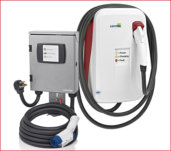
Figure 2 – Leviton’s Evr-Green® Electric Vehicle Charging Stations
“A GMI circuit has always been required with cord-connected EVSE with a 20 ma trip level,” said Brown, “but it’s not currently required on all hardwire-connected EVSEs.” And there are scenarios, according to Brown, where removing that safeguard would unnecessarily increase the risk of a hazardous condition.
The standard gap
“The issue is that the UL standard does not require a GMI circuit for all EVSEs,” explained Brown. “For example, if an EVSE offers a charge circuit interrupting device (CCID) that trips at 5 mA, as opposed to a 20 mA trip level, the GMI circuit may not be required by the standard. In most cases this must be a hard-wired EVSE application, and a special UL investigation is performed on the grounding circuit to prove it to be reliable.” Note: The 20 mA level is also permitted by adding double insulation requirements for the CCID.
The problem is that if a hard-wired system without a GMI circuit were wired incorrectly, the system could function normally even though it’s not grounded. And if somehow a line wire were then connected to either the metal housing of the EVSE or the metal chassis of the vehicle, it could expose that 240 V to human contact.
“There is the other safety circuit – the CCID,” said Brown. “Say your vehicle chassis is at 240 V and you touch the metal, the CCID is supposed to kick in and save your life. But why go that far? Why rely only on the CCID for the hard-wired systems when there are additional protections for cord-connected EVSE?”
After Brown identified the issue, Leviton submitted a proposal to UL, noting that the ground monitor test should be added to all hard-wired EVSEs as well.
How GMI works
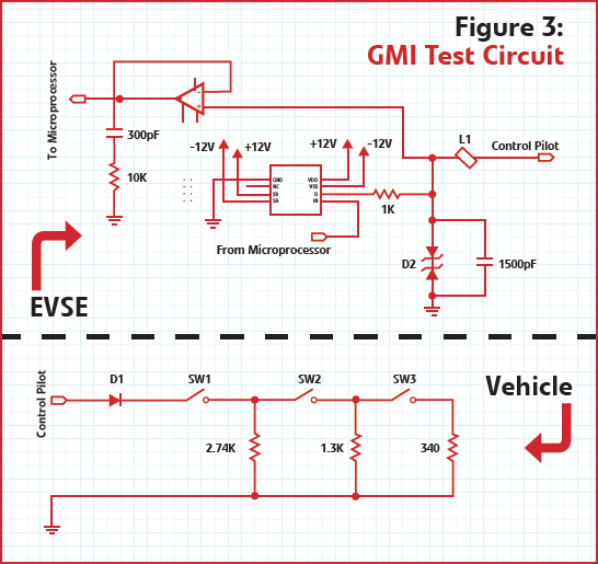
The GMI circuit – in a Leviton charging station, for example – is tested three times prior to allowing the vehicle to transition into the charging state. “The first test is performed during the power-up self-test sequence,” explained Brown. When the EVSE is turned on, the ground impedance is measured. If the impedance measured is too high, the fault light will illuminate, and the EVSE cannot be used until the problem is corrected.
“Once the GMI passes the power-on self-test, the EVSE can be plugged into a vehicle,” said Brown. “Then the circuit is tested in two steps to ensure that the ground is connected all the way from the vehicle chassis to the service panel where the circuit breakers are.”
The first test determines whether the ground is connected from the EVSE to the facility service panel. This incorporates a portion of the pilot wire circuit. If the ground impedance is too high, the state voltage will change to an out-of-tolerance condition and the fault LED will illuminate, indicating out-of-tolerance. Once the fault LED is illuminated, the EVSE cannot transition into a charging state until the issue is corrected.
The second test determines if the ground is connected from the EVSE to the vehicle. If the ground is open prior to power-up, the Leviton EVSE will show a fault as a result of the power-up self-testing performed by the EVSE.
Grounding certified
The existing UL test for GMI circuits determines the impedance on the ground path between the EVSE and the service equipment voltage. During the test, a potentiometer is placed on the ground path between the EVSE and the input voltage. Once the potentiometer is in place, starting from zero ohms, the resistance is increased until the EVSE stops the charging process.
Leviton EVSE includes a ground monitor circuit that’s connected from line to ground. The test sends a small current to ground, which is small enough to fall below the required maximum CCID current threshold of 20 mA. The transistor side of the opto-coupler is connected to a series of analog circuits that determines when the ground at the line side should be disconnected.
In Leviton’s case, the output ground monitor circuit is isolated from the main controller and it will function properly even if the controller stops functioning. The circuit detects impedance, so when the impedance in the output ground path is increased, the expected state voltages required (per the J1772 Recommended Practice) are not achieved, causing the EVSE to disconnect charging to the vehicle from the service equipment.

Change is imminent
Safeguards and life-safety devices are top priority for UL, and Brown believes that the recommended changes will be adopted soon. “I recently made presentations to the CANENA and to NEMA,” said Brown. “Most agreed that we should make this change and require GMI circuits for hard-wired EVSE. The ground monitoring circuit is a life-saving device. We believe it should be standard on all EVSEs sold in North America.”
Kenneth Brown is Director of Engineering at Leviton’s Commercial and Industrial business unit. He is Chair of the NEMA 5EV Technical Committee and Chair of the EVSE Embedded Metering and Communication working group. Ken is a member of the UL 1449 and UL 2231 Standards Technical Panel (STP), and a member of NEMA 5EV and 5VS Surge Protective Devices Technical Committee.
This article originally appeared in Charged Issue 15 – August/September 2014


