
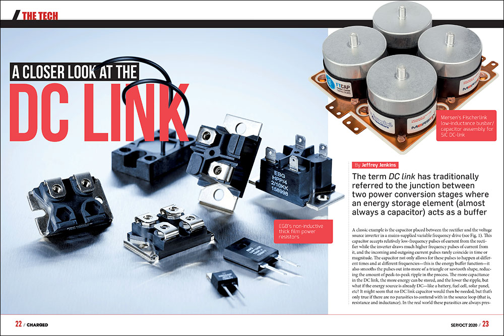
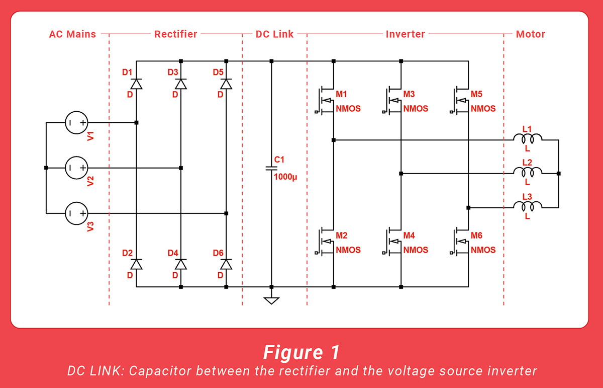
The term DC link has traditionally referred to the junction between two power conversion stages where an energy storage element (almost always a capacitor) acts as a buffer for each.
A classic example is the capacitor placed between the rectifier and the voltage source inverter in a mains-supplied variable frequency drive (see Fig. 1). This capacitor accepts relatively low-frequency pulses of current from the rectifier while the inverter draws much higher frequency pulses of current from it, and the incoming and outgoing current pulses rarely coincide in time or magnitude. The capacitor not only allows for these pulses to happen at different times and at different frequencies—this is the energy buffer function—it also smooths the pulses out into more of a triangle or sawtooth shape, reducing the amount of peak-to-peak ripple in the process. The more capacitance in the DC link, the more energy can be stored, and the lower the ripple, but what if the energy source is already DC—like a battery, fuel cell, solar panel, etc? It might seem that no DC link capacitor would then be needed, but that’s only true if there are no parasitics to contend with in the source loop (that is, resistance and inductance). In the real world these parasitics are always present, and while drawing (or supplying) pulsating current through a resistance only gives rise to more ripple voltage (similar to reducing the amount of capacitance, in fact), doing the same through an inductance causes voltage spikes at the beginning and ending of each pulse, because inductors resist any change in current through them by creating a voltage to oppose such a change (according to the classic inductor equation, -V = L * [dI / dt]).
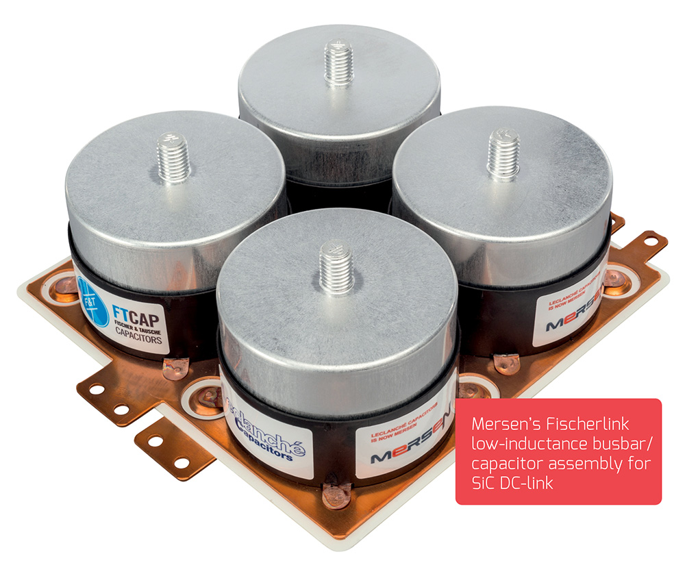
Putting things into a more concrete context, a modern traction inverter using SiC MOSFETs can switch from fully on to off, or vice versa, in less than 50 ns, and if that inverter didn’t have a DC link capacitor and was drawing 100 A pulses of current from the battery, then a mere 1 uH of inductance in the wiring (equivalent to about 1 m of wire in free space!) would give rise to spikes of 2,000 V at every transition (to paraphrase the most famous line from the movie Jaws, you’re gonna need a bigger switch…). With the DC link capacitor in place, however, the inverter will supply the rectangular pulses of current drawn by the switches and present to the battery a current waveform that is mostly DC with a bit of triangular ripple on top. Now it is only the stray inductance of the bus structure between the DC link capacitor and switches that will give rise to spikes at each transition, and with care this inductance can be reduced to 20 nH (i.e. by 50x) or less. In regenerating mode, a similar situation applies, except this time the inverter is operating as a boost converter, presenting a relatively low ripple current load to the motor while delivering sharp, rectangular pulses to the battery. The DC link capacitor performs the same functions and needs the same basic specifications, just with the direction of the current reversed.
If that inverter didn’t have a DC link capacitor and was drawing 100 A pulses of current from the battery, then a mere 1 uH of inductance in the wiring would give rise to spikes of 2,000 V at every transition.
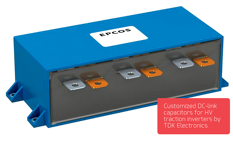
Obviously the DC link capacitor must itself have low inductance if it is to be effective, but it also needs to have low internal resistance (or ESR, for Equivalent Series Resistance), otherwise the AC component of the current waveform (i.e. the ripple) will cause it to overheat from I2R losses. In the bad old days, the only real choice of capacitor for high-power applications was the can-style aluminum electrolytic, which features an extremely high capacitance per unit volume, but with rather unimpressive ESR specs due to the relatively high bulk resistance of its electrolyte. This made (and still makes) “elkos” ideal for mains-supplied applications, because considerable capacitance is needed to smooth out the low-frequency ripple from mains rectification, and that all but assures that there will be a sufficiently low ESR to keep heating from both the low- and high-frequency ripple components under control. For the traction drive in an EV, however, there is no low-frequency ripple from mains rectification, of course, so relatively little capacitance is actually needed—just enough to decouple the battery loop inductance and filter the high-frequency ripple reflected from the inverter, in fact. Capacitors with a plastic film dielectric (especially polypropylene), however, feature extremely low ESR (because current does not have to pass through an electrolyte), while their much lower capacitance per unit volume is not much of a downside when the source is already DC. Furthermore, there is a practical upper limit on the voltage rating for elkos of around 450 V (higher is possible, you just pay dearly for it), whereas the opposite situation applies to film capacitors—the dielectric strength per unit thickness is so high for most plastics (15-40 kV/mm) that it is impractical to go below a certain voltage rating.
The extremely low ESR of film capacitors is mostly a plus for DC link applications, but one potential issue is the exacerbation of resonance effects, especially in multi-drive systems. Any time an inductor (e.g. the battery loop inductance) meets a capacitor (e.g. the DC link capacitance), a resonant network is formed, and this can resonate (or “ring” in the argot) when hit with a steeply rising pulse of current. However, there needs to be a reasonable balance between the inductance and capacitance for resonance to occur, and the LC network can’t be loaded down too much (or “damped” in the argot). The relatively high ESR of elkos actually helps them dampen out any ringing, while the very low ESR of film capacitors has the opposite effect. In some cases, one is forced to resort to the rather perverse solution of intentionally increasing the ESR of some or all of the film capacitors in the DC link to effectively form a parallel damping network. The resistance in a parallel damping network must have extremely low self-inductance to be effective (e.g. something like a disc of resistive material in between the capacitor studs and bus plates) and it will get hot in normal operation, which the capacitors won’t like one bit, so this presents what the military likes to euphemistically call “an opportunity to excel.”
Another major consideration is the pre-charging of the DC link capacitance. At relatively low voltages (<36 V or so), turning on a switch which directly feeds a capacitor might be okay, but at the >350 V typical of most EV traction batteries, that’s just asking for trouble. The issue is inrush current, which can be estimated with Ohm’s law as I = V / R, where V is the difference between the supply and capacitor voltage and R is the total loop resistance, including the ESR of the capacitor as well as the internal resistance of the battery. Unlike with resonance effects, however, the additional ESR of aluminum electrolytics is unlikely to be of much help here—after all, if the battery loop resistance is 100 mΩ then inrush will be on the order of 3500 A! Modern hydrogen-filled contactors are good at handling high peak currents, yes, but not that good. This extreme amount of inrush can also excite resonances when there otherwise wouldn’t be enough inductance present (because energy stored in an inductor is proportional to I2). The solution is to slowly charge up the DC link capacitance via a resistor before closing the main contactor, or pre-charging, and while it seems fairly straightforward at first glance, implementing it in the real world can be a real headache, starting with the deceptively difficult question of the power rating for the resistor.
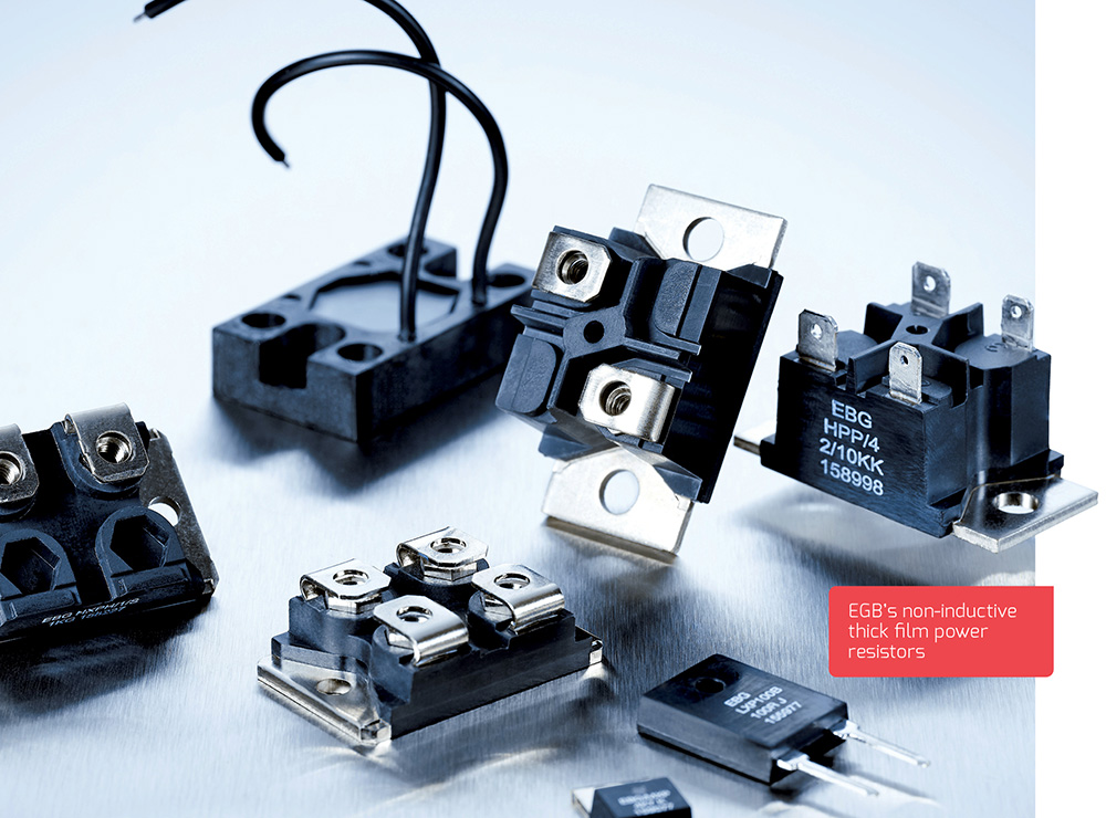
If subjected to a continuous voltage, a resistor must be rated to dissipate at least as much power as determined by Ohm’s law (P = V2 / R), but the current through a resistor charging a capacitor decreases as the voltage on the capacitor rises, and the time to complete charging is estimated as 5RC (that is, five RC time constants). For example, if a 500 uF DC link capacitor needs to be brought up to 350 V within 2 seconds (storing 30.6 J in the process), this requires a resistance of 800 Ω and the ability to withstand a peak power of 153 W (and a peak current of ~0.44 A). The average power dissipated by the pre-charge resistor depends on how often this cycle is repeated, however, and coming up with a reasonable estimate of that is where the headache begins. Let’s assume that our EV customers won’t try cycling power more often than every 10 seconds (though my experience tells me otherwise…), then the average power dissipated in the pre-charge resistance will be a mere 3 W. That would seem to suggest that a 5 W resistor should suffice here, but that very much depends on the specific construction of said resistor. More specifically, wirewound resistors are renowned for handling high peak powers and brief overloads compared to other constructions, so they excel at pre-charge duty (though metal oxide resistors are very suitable as well). The types that don’t do so well here are the various spiral or serpentine resistive film constructions, whether through-hole or surface-mount. One possible exception is the planar thick film type, in which a sheet of resistive material is deposited onto a ceramic surface, as it should have a very high peak-to-average-power rating.
Regardless of the construction, if the resistor datasheet gives a short-term overload rating, then it is possible to evaluate it for pre-charge duty. For example, one datasheet for a metal oxide resistor gives both a short-term overload rating of 2.5x the working voltage for 5 seconds, and a pulse power rating of 4x working voltage for 1 second with 25 seconds rest (where “working voltage” is also from Ohm’s law, V = [PR]0.5). Converting both overload ratings into energy (watt-seconds/Joules) gives ~156 J for the 5 s overload, but just 80 J for the 1 s pulse, hence one should be very wary of extrapolating the peak power down to shorter periods of time than given in the datasheet. The benefit in going with wirewound over metal oxide is clearly exemplified in one datasheet covering both types of resistors from the same manufacturer. It states that the wirewound versions can withstand 10x rated power for 5 seconds, while the metal oxide versions can take 5x rated power for 5 seconds, or half as much. That suggests that a 3 W wirewound resistor from this series could be used—the energy rating is 3 W * 10x * 5 s, or 150 J, which far exceeds the 30.6 J stored in our example—but keep reading the fine print, because the 3 W size is limited to 250 V max, while the 5 W size could just scrape by on its 350 V max rating. Likely the 5 W size would be okay here, but I can’t help but be reminded of another classic movie quote, this time from Dirty Harry: “You’ve got to ask yourself one question: ‘Do I feel lucky?’ Well do ya, punk?”
Read more EV Tech Explained articles.
This article appeared in Charged Issue 51 – September/October 2020 – Subscribe now.