
The electronically-switched reluctance motor – often shortened to the switched reluctance motor, or SRM – has been gaining in popularity over the last decade because it is simple, robust, and arguably the least expensive of all motor types to manufacture. The reasons for the relatively late blooming of the SRM – the first reluctance motor was built in the 1800s by W.H. Taylor, after all – are that they are notoriously difficult to control and are often prone to emitting significant amounts of acoustical noise while in operation.

Much research is underway to tackle these problems, though, and with a bit more refinement the SRM just might become the prime choice for the traction motor in electric vehicles. The renowned Sir James Dyson, of Dyson Vacuum fame, developed and commercialized an SRM for a handheld vacuum that spun at a blistering 104,000 rpm, but it is somewhat telling – and, perhaps, cautionary – that Dyson appears to have gone back to a more traditional “brushless” motor design in subsequent models.
The physical principles behind the reluctance motor are fairly simple. The first is that the magnetic analog of current, called flux, wants to travel the path of least magnetic resistance, called reluctance. The second is that low reluctance materials like iron and its alloys, nickel, cobalt, etc., tend to strongly align to an incident magnetic field.
Thus a reluctance motor merely has a rotor with alternating regions of high and low reluctance on it, and a stator with several electromagnets that when energized in sequence (and regardless of polarity!) will pull the low reluctance regions, or poles, along.
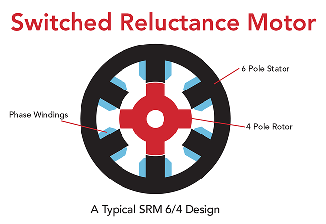
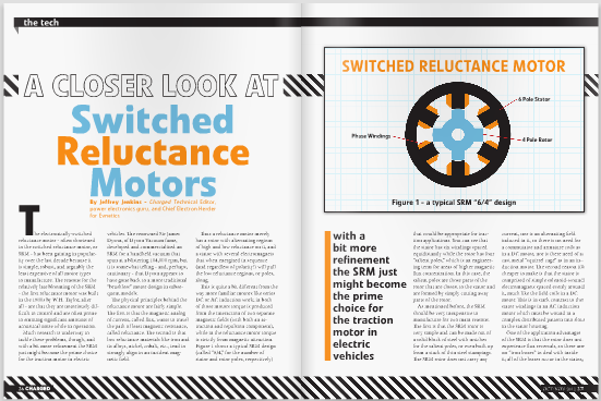
This is quite a bit different from the way more familiar motors like series DC or AC induction work; in both of those motors torque is produced from the interaction of two separate magnetic fields (with both an attraction and repulsion component), while in the reluctance motor torque is strictly from magnetic attraction. Figure 1 shows a typical SRM design (called “6/4,” for the number of stator and rotor poles, respectively) that would be appropriate for traction applications. You can see that the stator has six windings spaced equidistantly while the rotor has four “salient poles,” which is an engineering term for areas of higher magnetic flux concentration. In this case, the salient poles are those parts of the rotor that are closest to the stator and are formed by simply cutting away parts of the rotor.
As mentioned before, the SRM should be very inexpensive to manufacture for two main reasons. The first is that the SRM rotor is very simple and can be made out of a solid block of steel with notches for the salient poles, or even built up from a stack of thin steel stampings. The SRM rotor does not carry any current, nor is an alternating field induced in it, so there is no need for a commutator and armature coils as in a DC motor, nor is there need of a cast metal “squirrel cage” as in an induction motor. The second reason it’s cheaper to make is that the stator is comprised of simple solenoid-wound electromagnets spaced evenly around it, much like the field coils in a DC motor. This is in stark contrast to the stator windings in an AC induction motor which must be wound in a complex distributed pattern into slots in the stator housing.
One of the application advantages of the SRM is that the rotor does not experience flux reversals, so there are no “iron losses” to deal with inside it; all of the losses occur in the stator, which is much easier to cool. This unipolar fluxing of the rotor also means it is perfectly acceptable to stall the SRM without damaging it, useful for holding a vehicle still on an incline or “proving” a load on a crane.
Things are not so clear-cut from the perspective of the controller for the SRM, however. The first big difference is that the SRM requires unipolar excitation, not the bipolar (AC) excitation required by induction motors (and which the commutator in a DC motor synthesizes, by the way). This means a different power stage design is required for the SRM controller.
One typical configuration is to wire each phase between the output terminals of two complementary switch/diode chopper modules (i.e., one module with the switch on top and the other with the switch on the bottom). The upshot of this is that you end up using twice as many modules as compared to the single half-bridge needed for each phase in an AC inverter, but you can drive each phase of the SRM with the full DC supply voltage.
A worse problem for the SRM controller is that the inductance of each phase is proportional to the degree of alignment with the salient poles of the rotor. As one or more rotor poles line up with a given stator winding, the inductance of that winding shoots up, making it harder to push the correct amount of current through it at the correct time. Conversely, as the rotor pole moves away from the winding, its inductance once again drops. The worst thing about this is that rotor torque will only be positive as current is supplied to the winding when inductance is increasing; the torque turns negative – i.e., regeneration occurs – when the inductance is falling. Thus, small timing errors in the delivery of current to each winding can result in less torque than expected, vibrations from the torque being inconsistent from phase winding to phase winding, or even from it going negative every so often.

The rotor position must be known (or predicted) with a high degree of accuracy, and the current control loop for each winding must be very fast – much faster than in an AC induction motor inverter – to get the best performance from the SRM.
Also, the effects of the change in the resistance of the windings with temperature, as well as the non-linear relationship of phase angle and winding current must be accommodated.
All of these demands add up to a very computationally-intensive control strategy for the SRM, which more or less explains why they have been sitting on the dusty shelves since the 1840s – there simply wasn’t enough computing power in programmable logic or microcontroller ICs to operate them until very recently.
The final disadvantage to the SRM, and perhaps the most difficult to address without also increasing the manufacturing cost and/or the controller complexity, is its tendency to emit a lot of noise in operation.
One of the main sources of noise is the stator being squeezed towards the rotor by the attractive force exerted by each phase pole pair as it is energized. An obvious solution to this is to make the stator stronger – i.e., use more material, which, of course, costs more. A less-obvious approach is to inject current into “inactive” windings at precise points in time to partially cancel the force vector from the active windings.

Some of the acoustic noise and vibration from the SRM is the result of the torque output having a lot of “ripple.” Especially unfortunate is the fact that the more one optimizes the SRM for high average torque output (by using a lower number of stator and rotor poles, which is unintuitive for those familiar with AC induction motors), the more torque ripple results.
All in all, the pluses of the SRM design are pretty compelling – cheap to manufacture, low to non-existent rotor losses, robust power stage topology – while the disadvantages, such as control algorithm complexity and high vibration and noise, do not seem insurmountable, especially when used as traction motors for electric vehicles.
Read more EV Tech Explained articles.
This article originally appeared in Charged OCT/NOV 2012 Issue – Subscribe Here.